Thread: 55 Wagon Progress
-
10-10-2013 09:41 PM #91
Thanks for the comments guys. Well, that's about enough of the practice pieces, time to finish the rest of the bends. Just to make sure we don't need any "tweaking", I'll cut a profile sample out of the center. This spot weld one the inner flange is far enough away so I won't need to grind out a spot weld, and still have enough of that flange for a good measurement. In other words, removed with minimal effort where it still holds it's shape accurately.

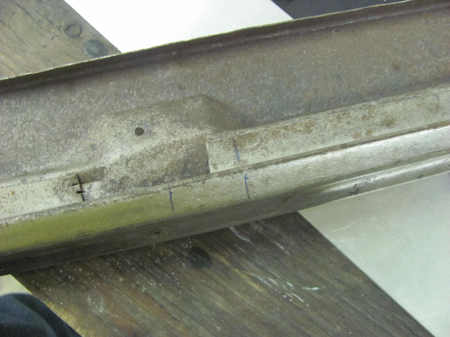

Our profile template:
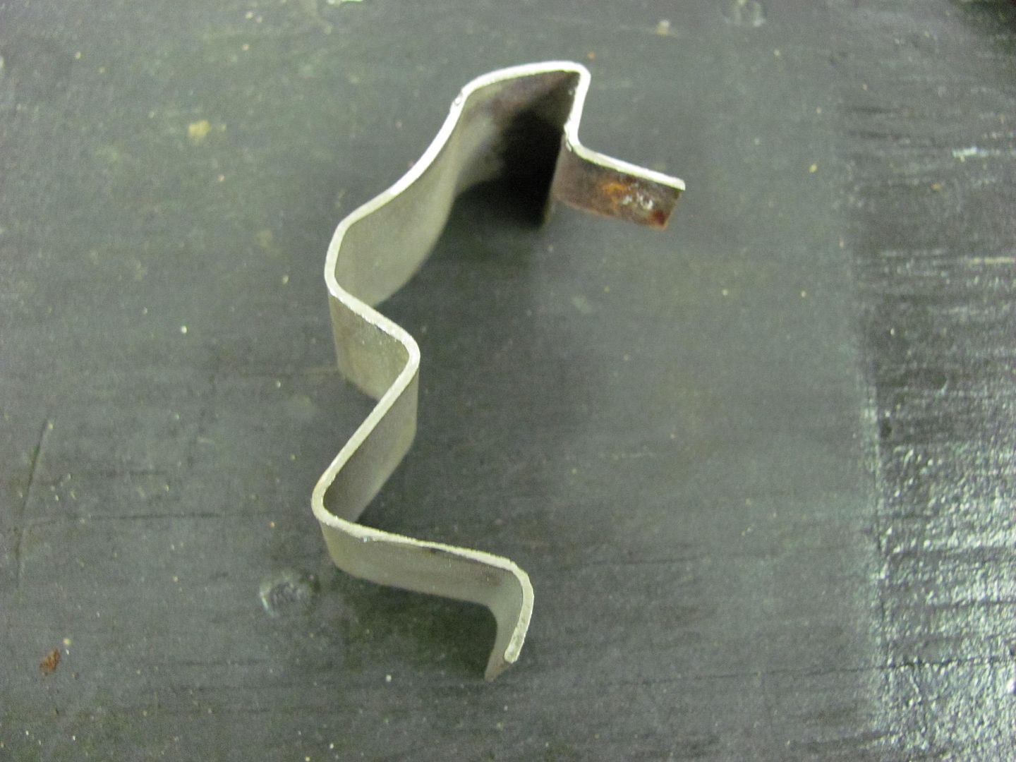
Just to compare to our test sample, looks like the inner flange was bent down a bit much in the manual hammering, will have to ease up a bit...
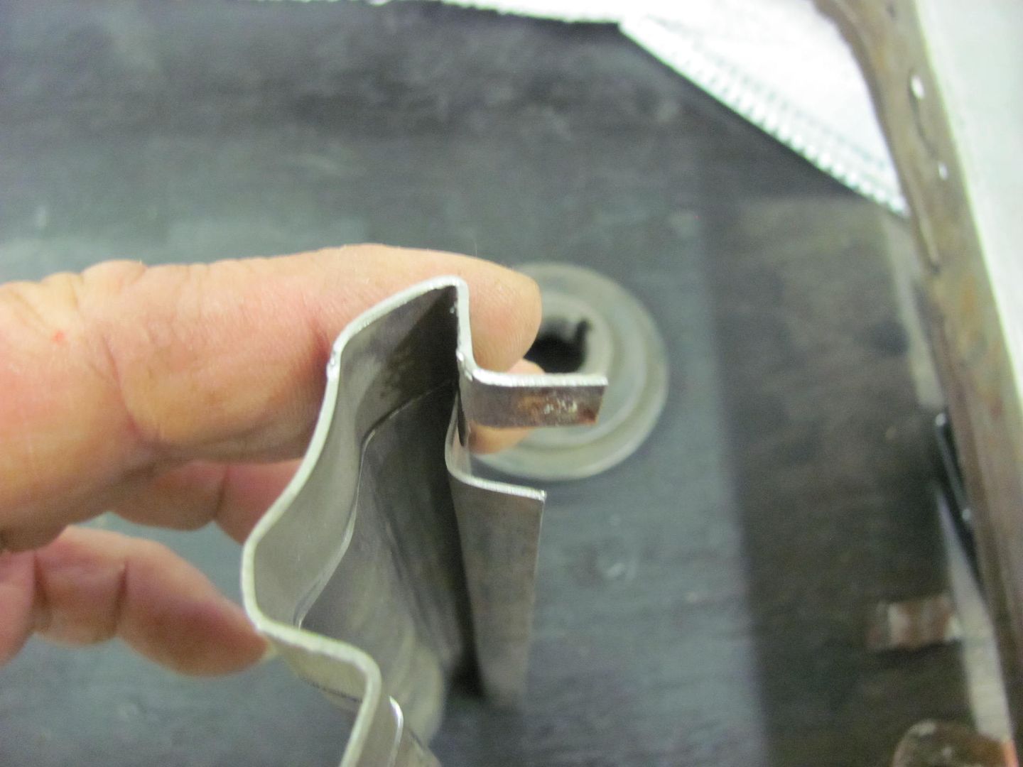
Outside profile looks good enough to leave alone!

Following the measurement used on the test sample, the panel is run through the bead roller's tipping wheel nice and slow to give us an initial mark for the bend, then repeated to tip the flange downward...
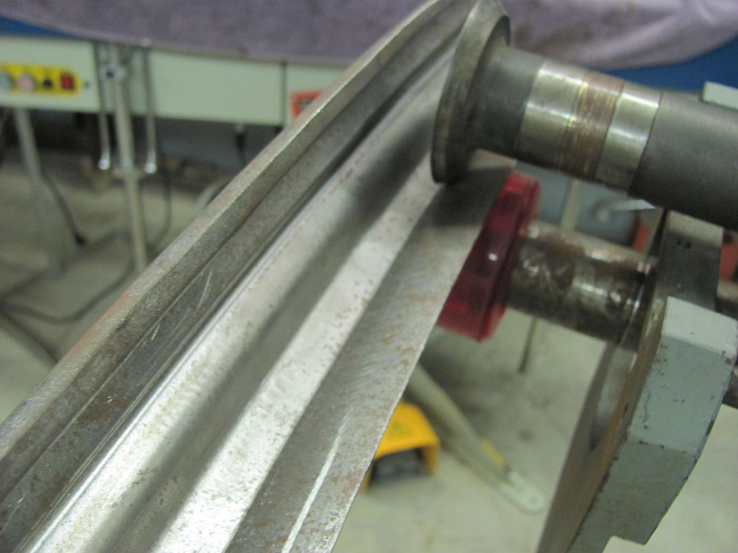
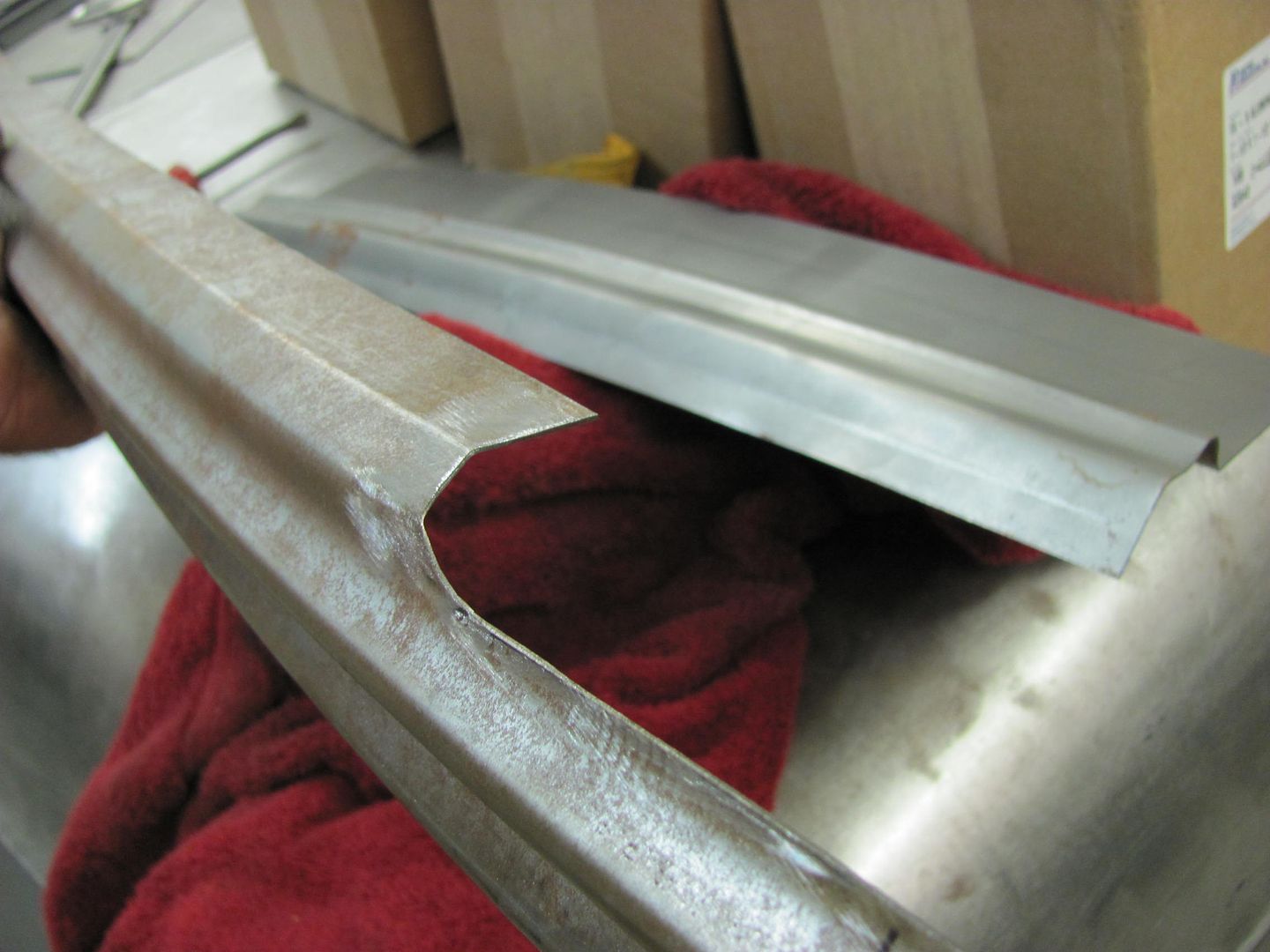
This looks about all we'll get without distorting and pulling, so then it's off to the custom anvil...
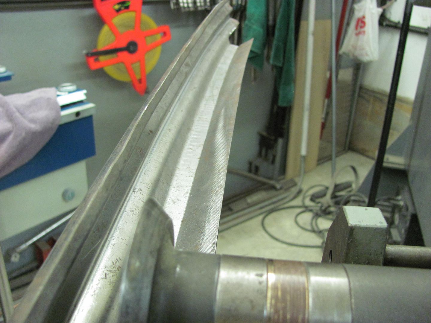
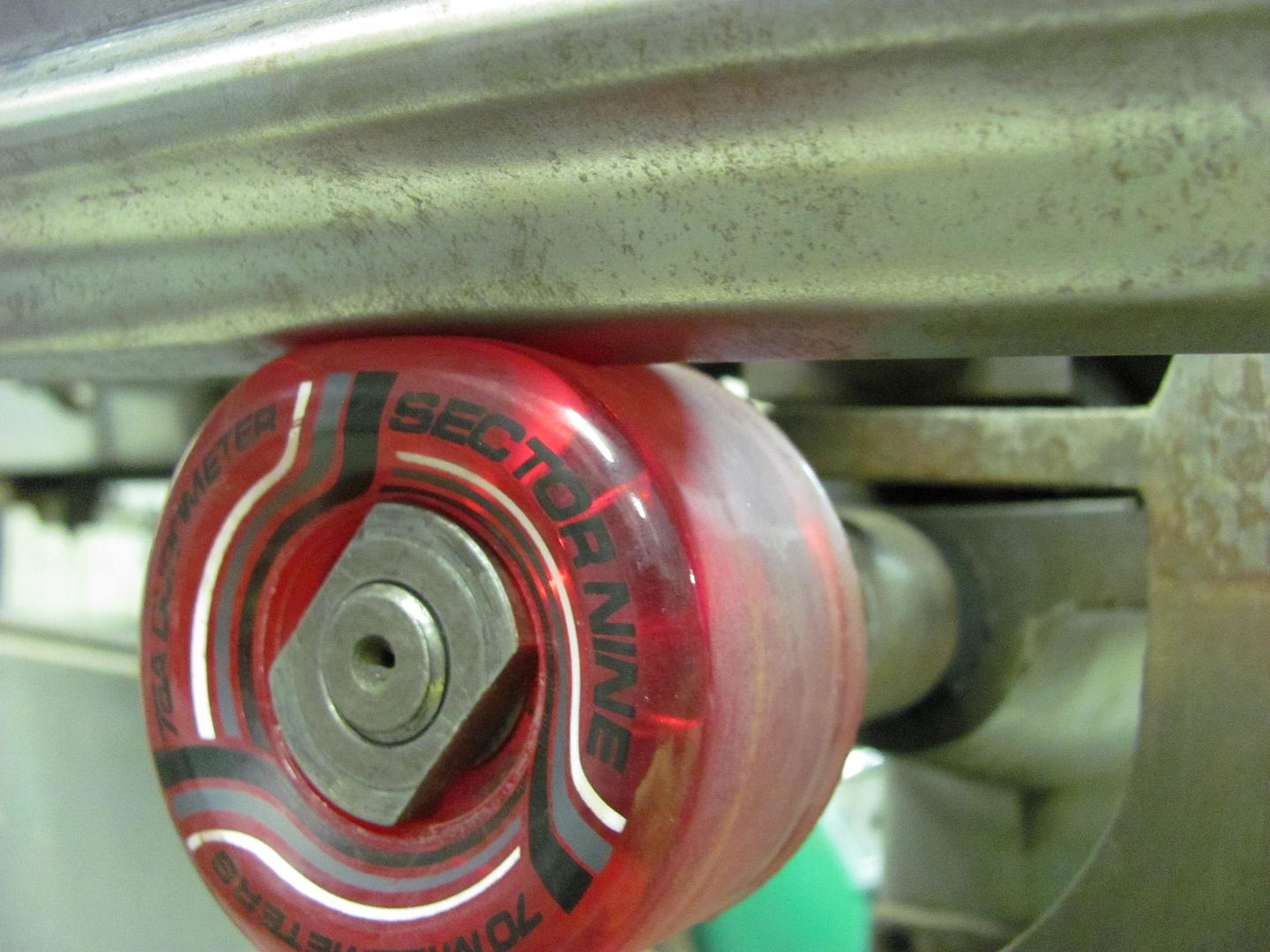
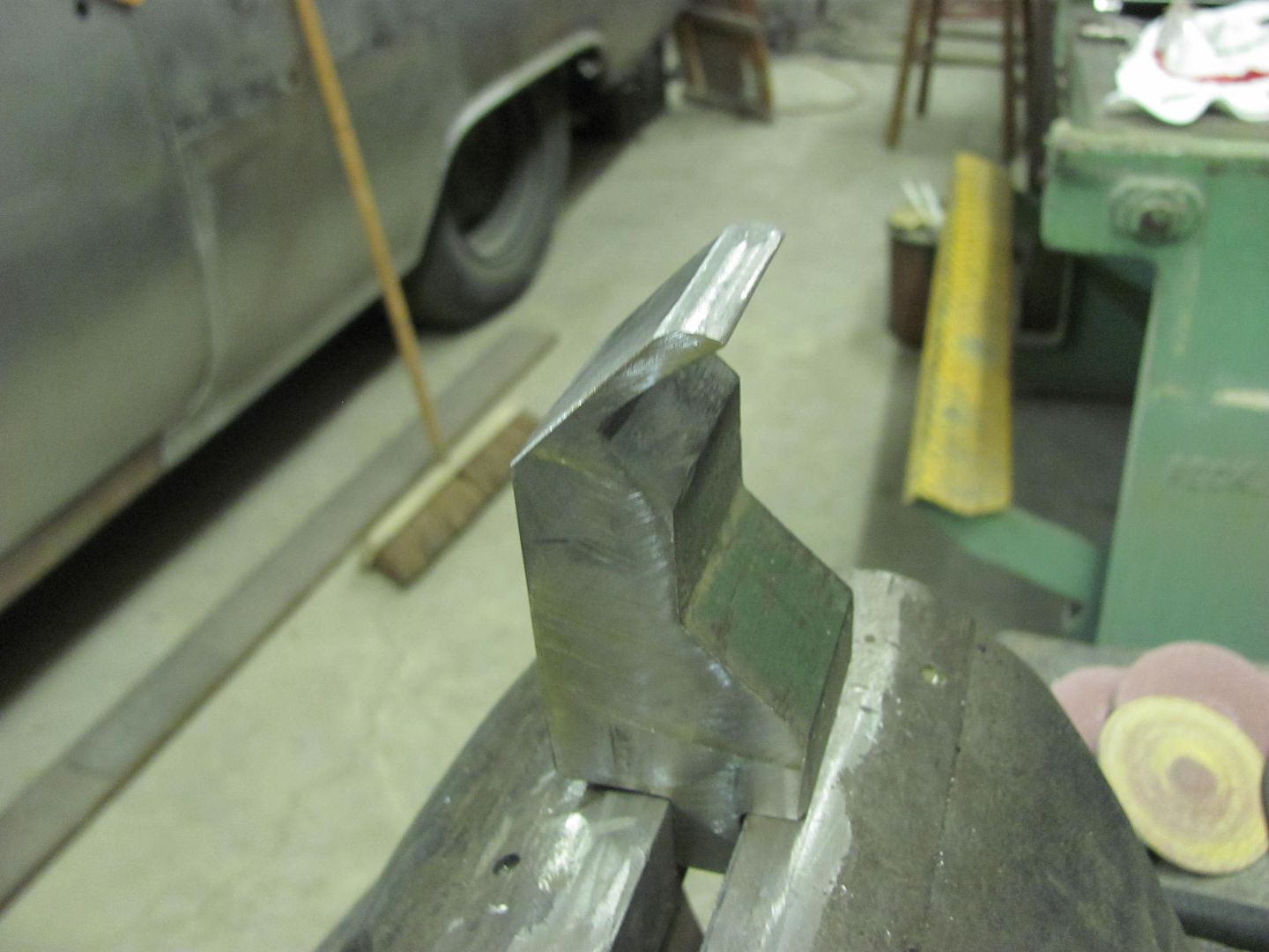
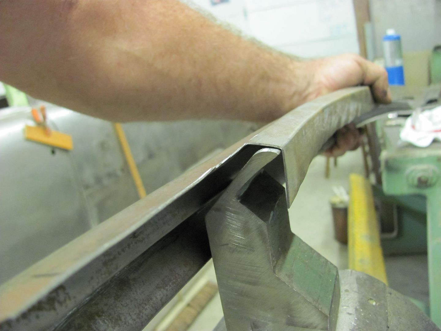
Then for some manual tipping...

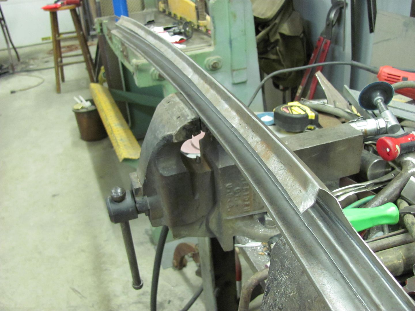
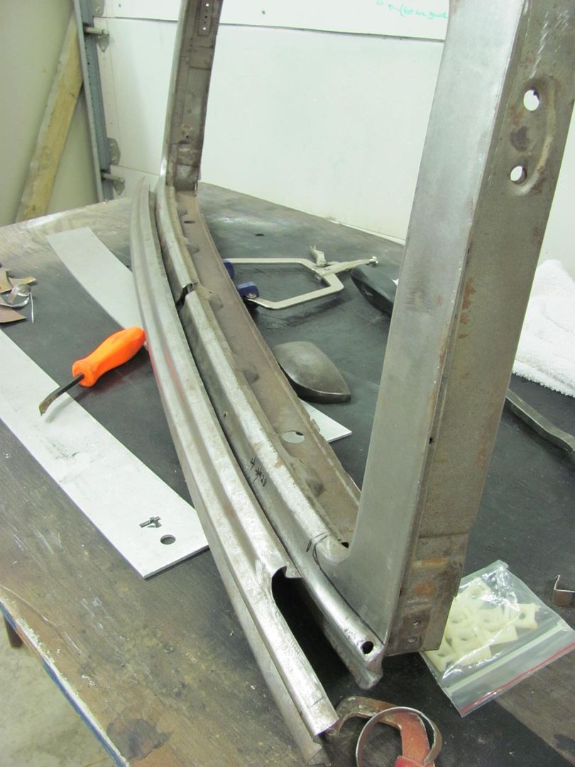
...and comparing to our profile sample......
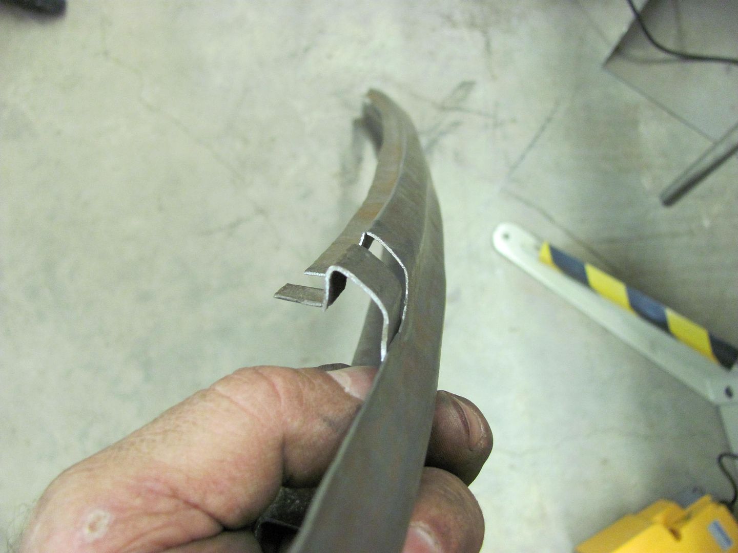
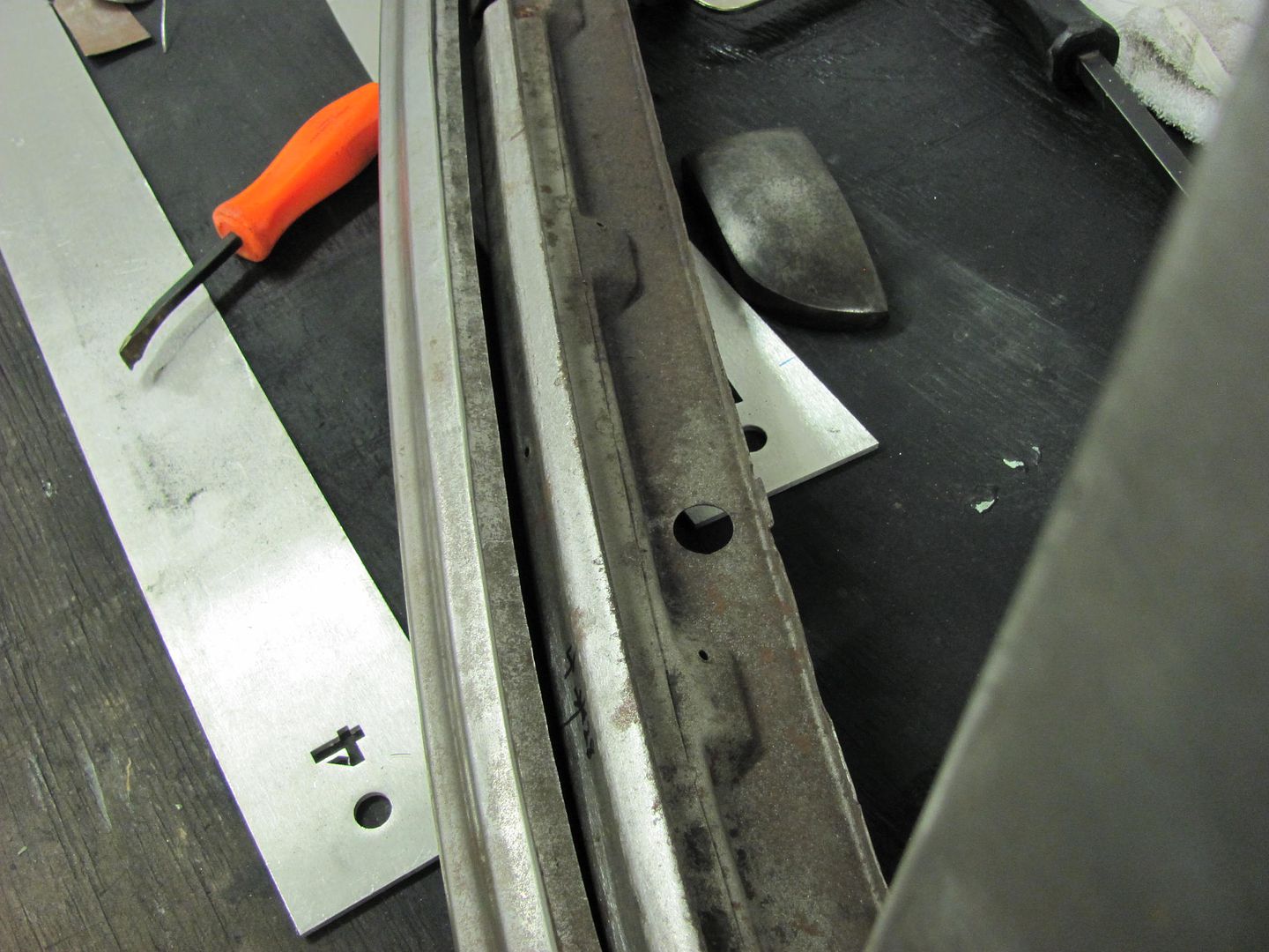
Ready to cut off the old next time...
Robert
-
Advertising

- Google Adsense
- REGISTERED USERS DO NOT SEE THIS AD
-
10-11-2013 03:28 AM #92
Nice work as always, Robert! I especially like your use of scratchbuilt fab tools and templates, should inspire others to try some fab work on their own and not just give up when they can't find what they need at their favorite 1-800-Hot-Rods mail order place!!!!!Yesterday is history, tomorrow is a mystery, Live for Today!
Carroll Shelby
Learning must be difficult for those who already know it all!!!!
-
10-11-2013 08:39 PM #93
Thanks Dave!
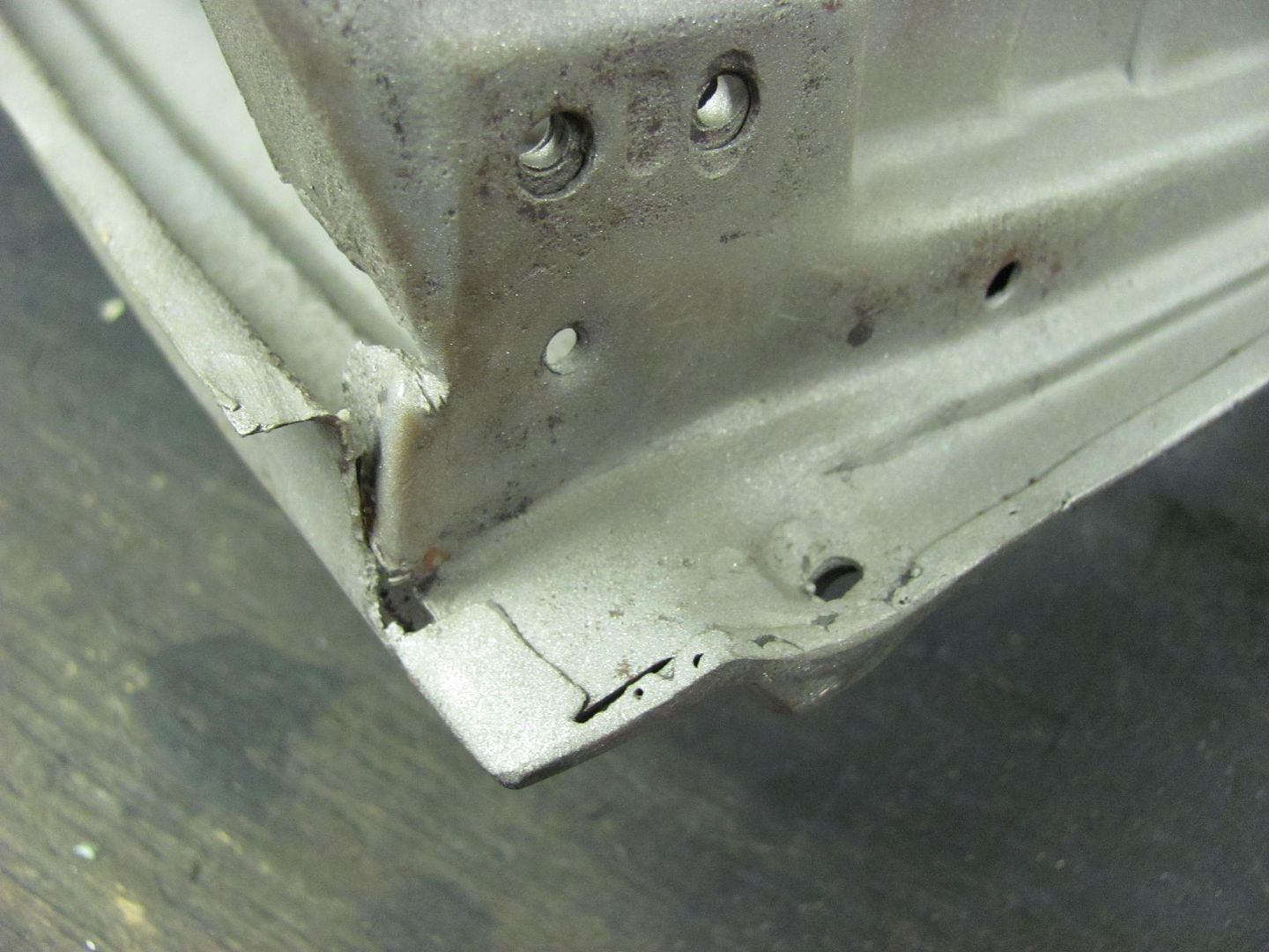
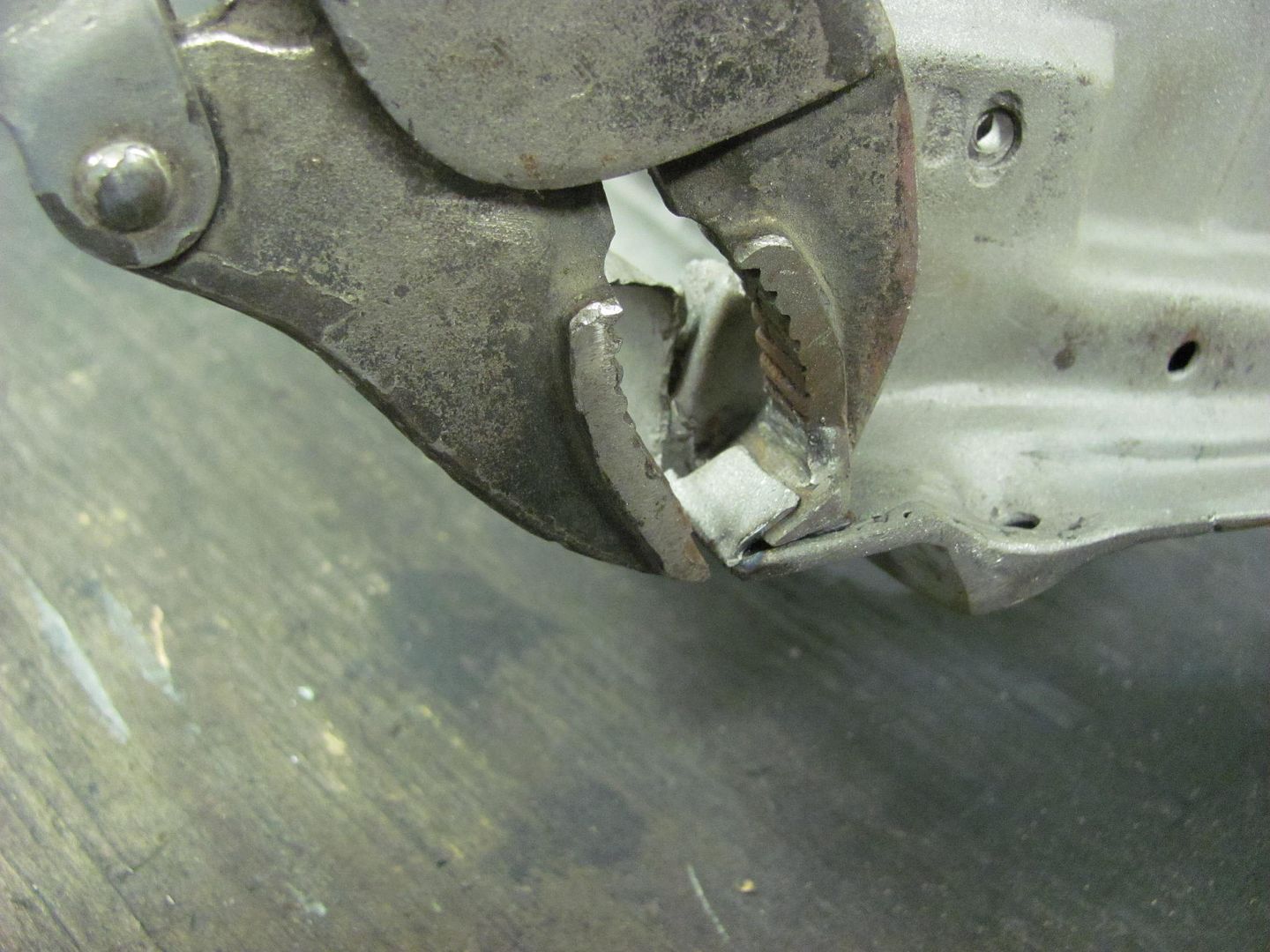
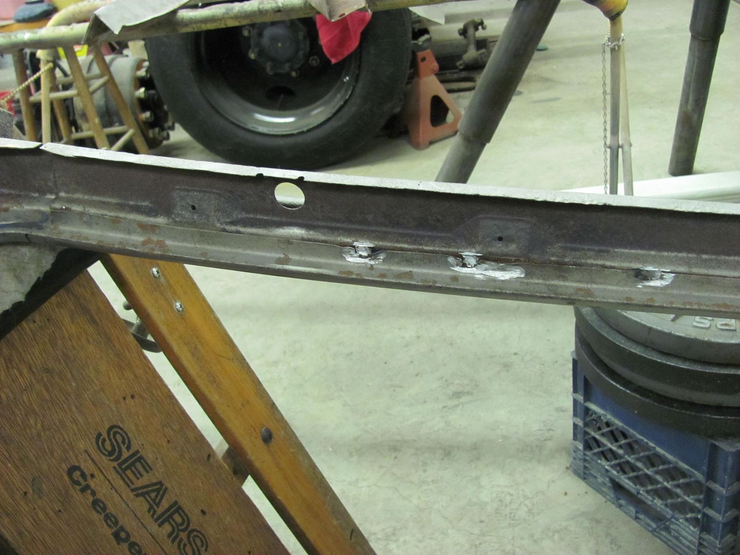
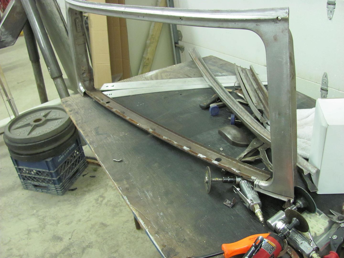
Well tonight's task was to remove the bottom detail of the lift gate and sandblast the remaining structure in prep for epoxy primer. The lower edge did have a flange folded up, so a slit was cut along the edge and the door skin vise grips were put to use...

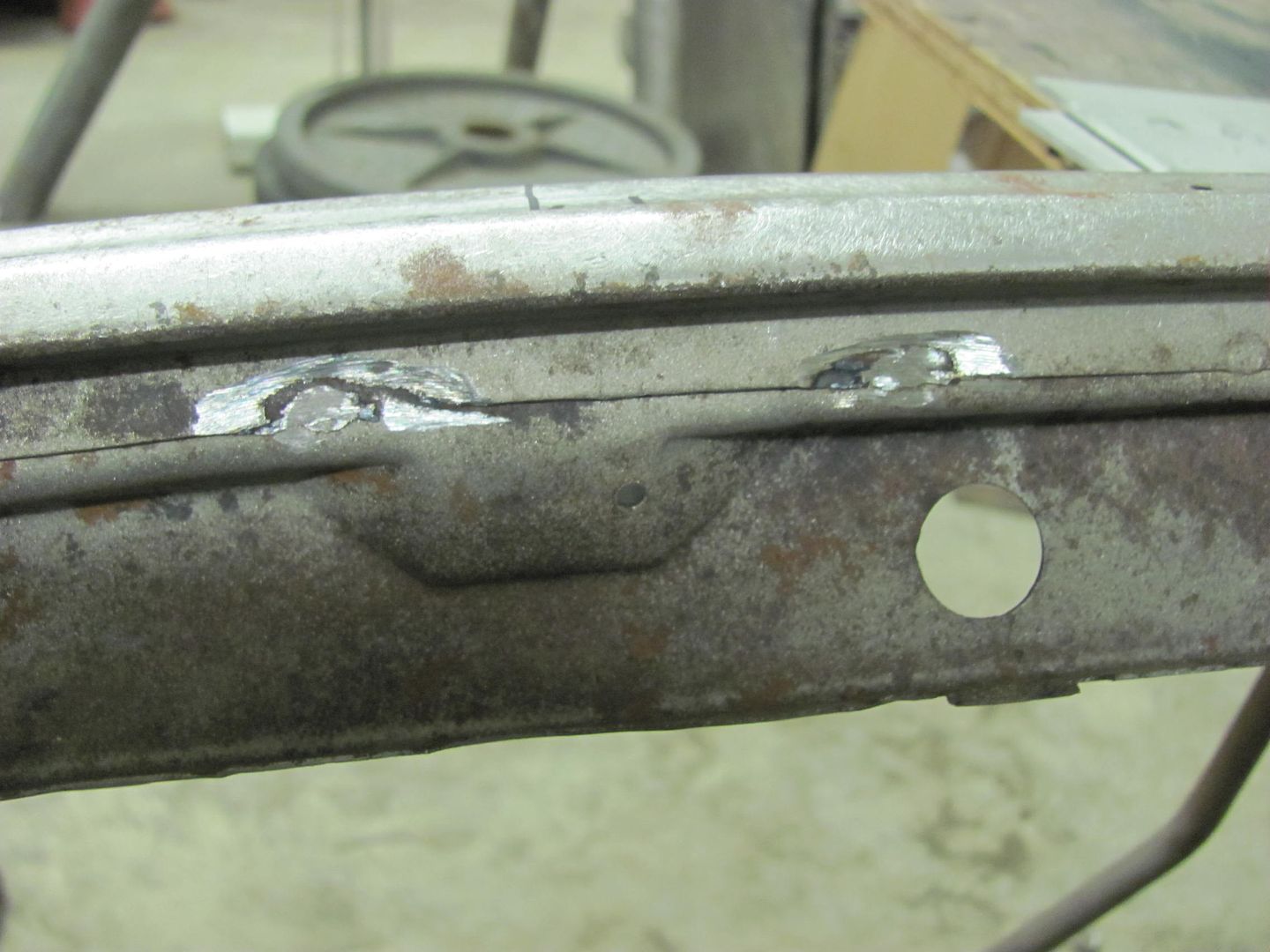
Next, the spot welds inside were ground out.....
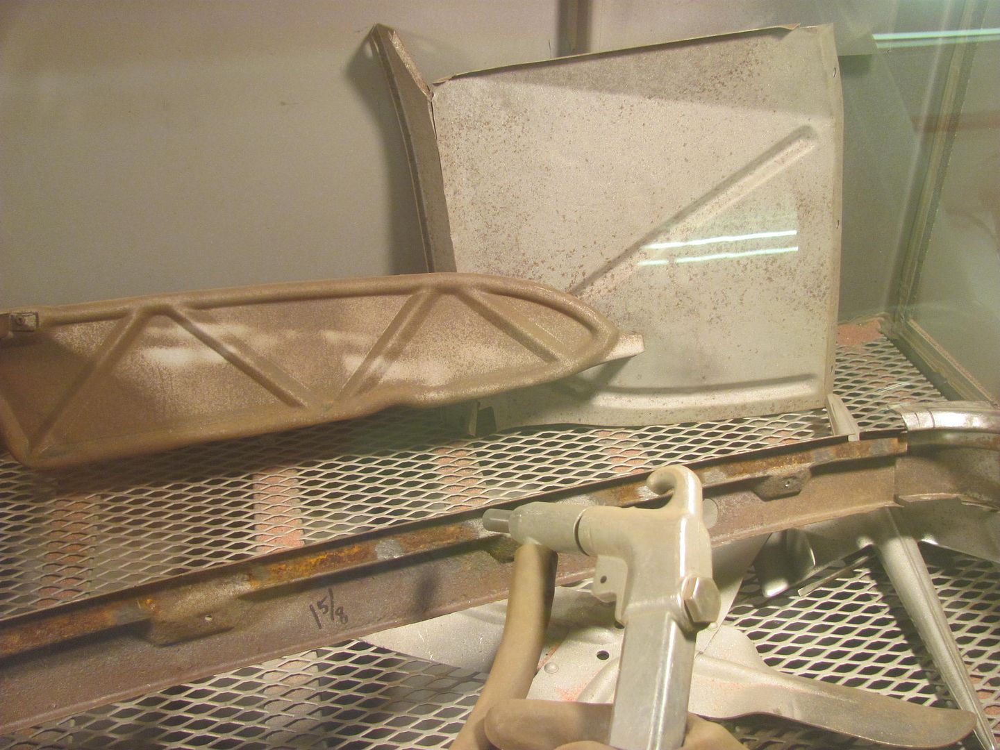
Media blasting..... nice to finally see through the glass!
The media blasting revealed a few more holes, and numerous pits, many of them close to breaking through.
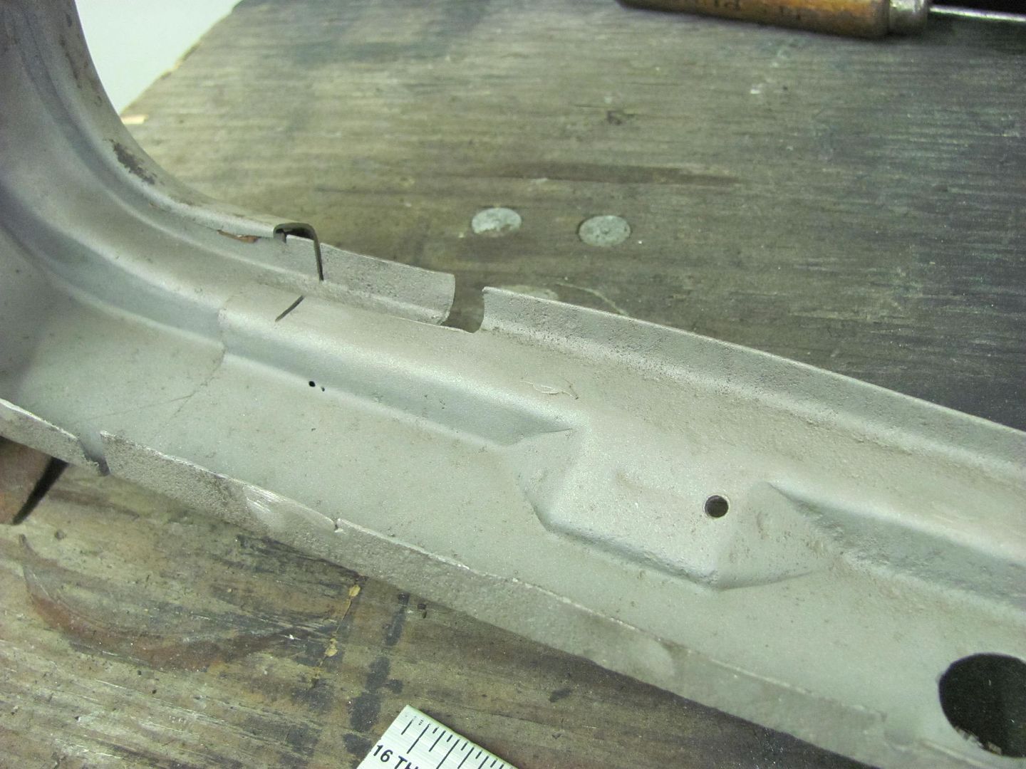
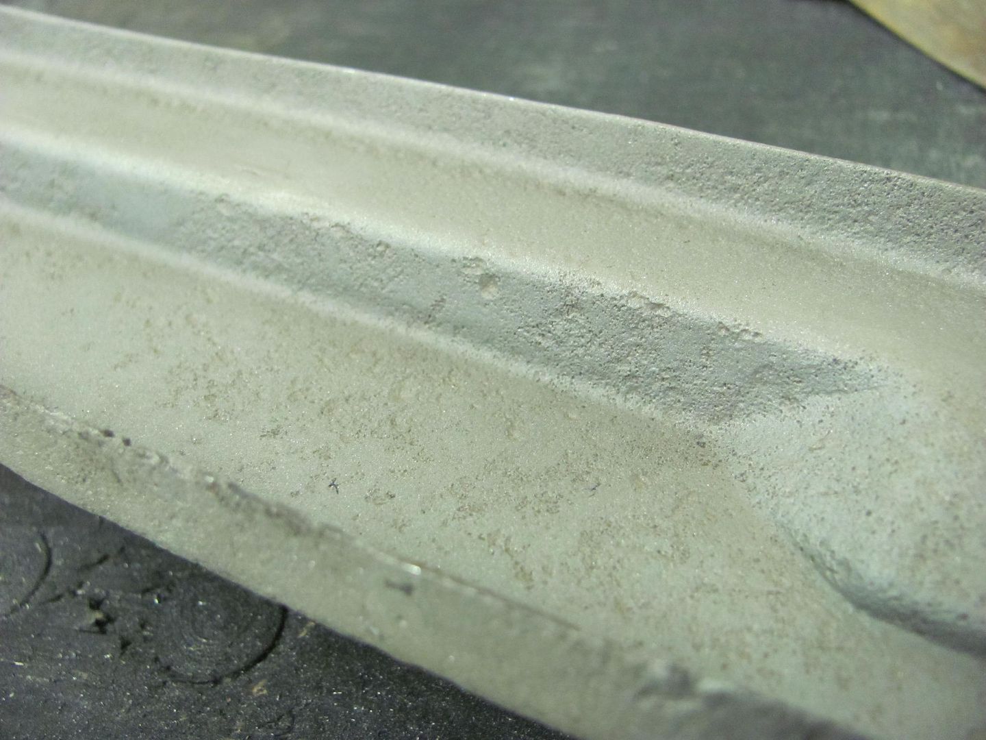
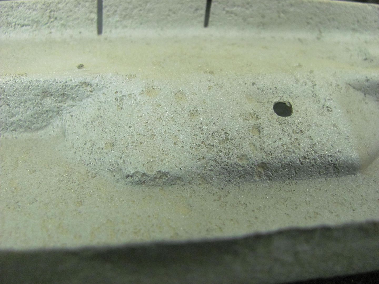
With all the other new metal going in the bottom, there's only one thing to do. Using the tipping wheel..........
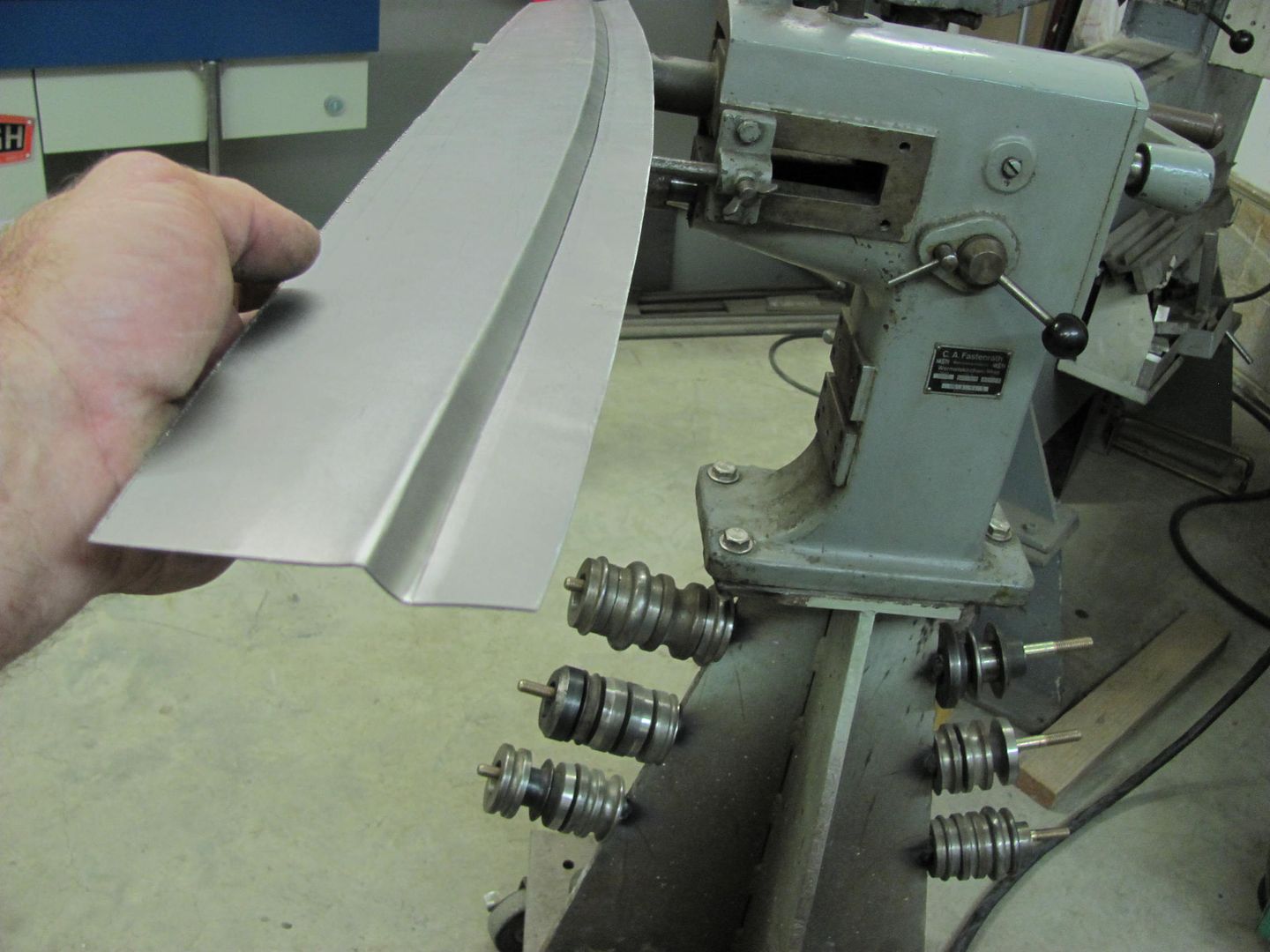
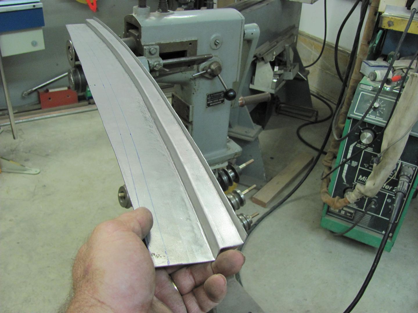

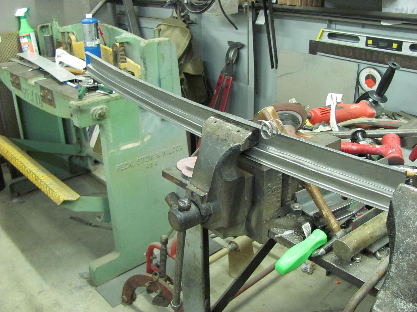
Comparing to the pitted version.....
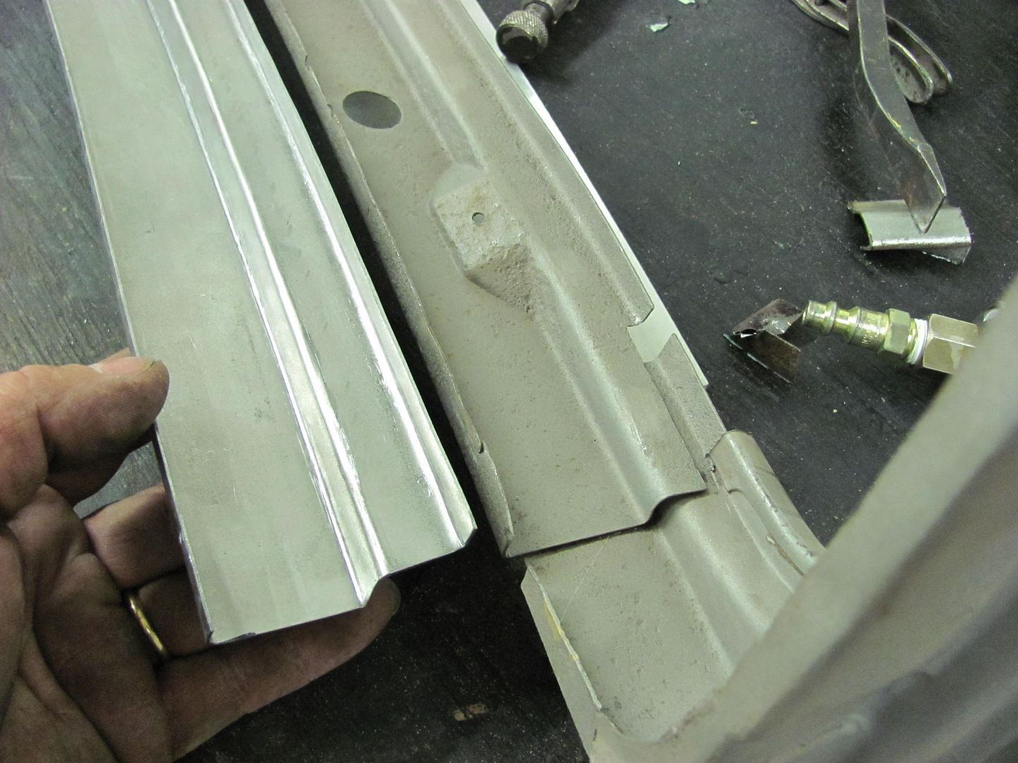
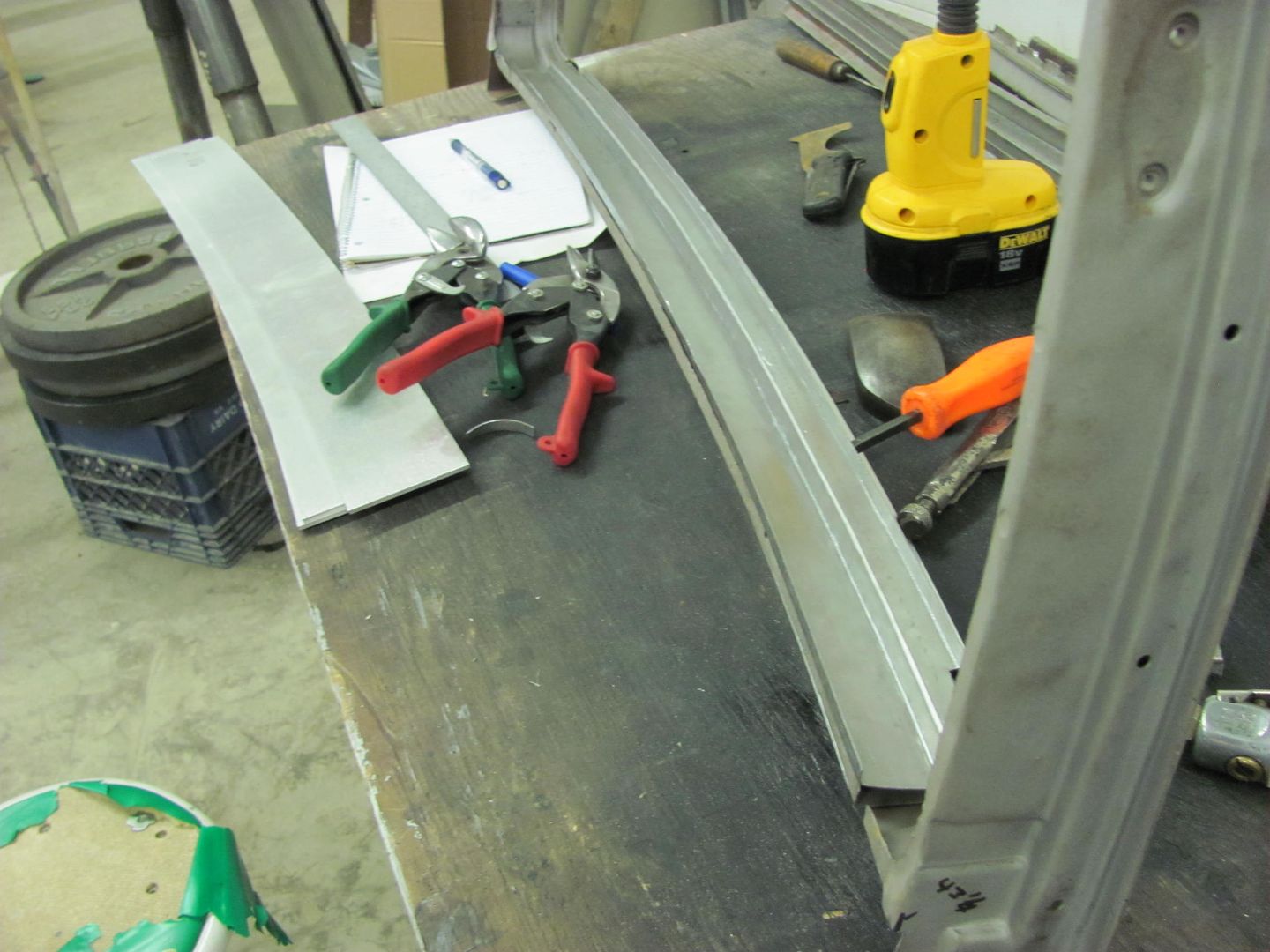
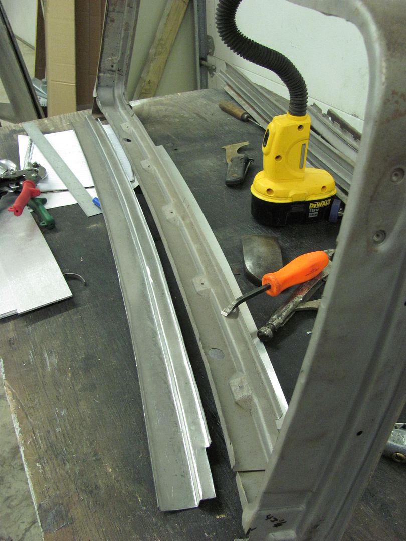
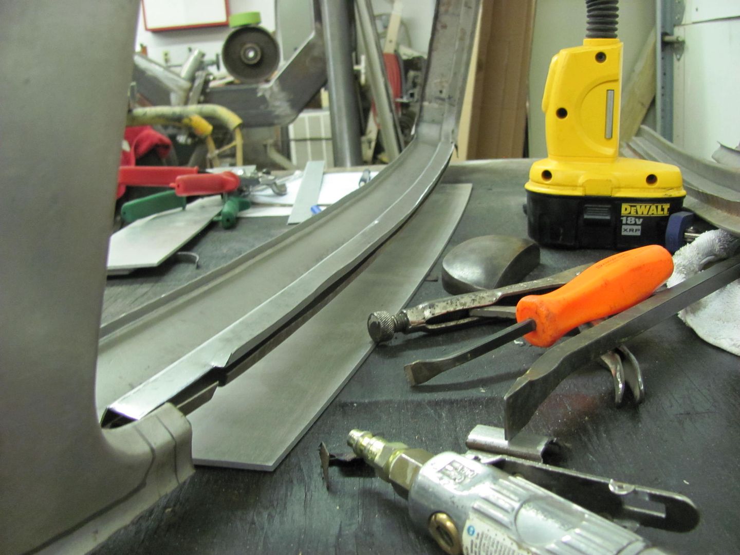

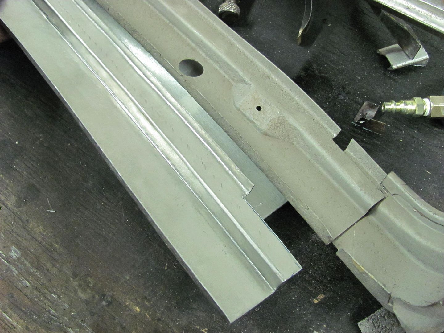
Next we'll need to do some corking to add the trim hole pad details.Robert
-
10-12-2013 09:36 PM #94
Now to address the mounting pads for the window molding....
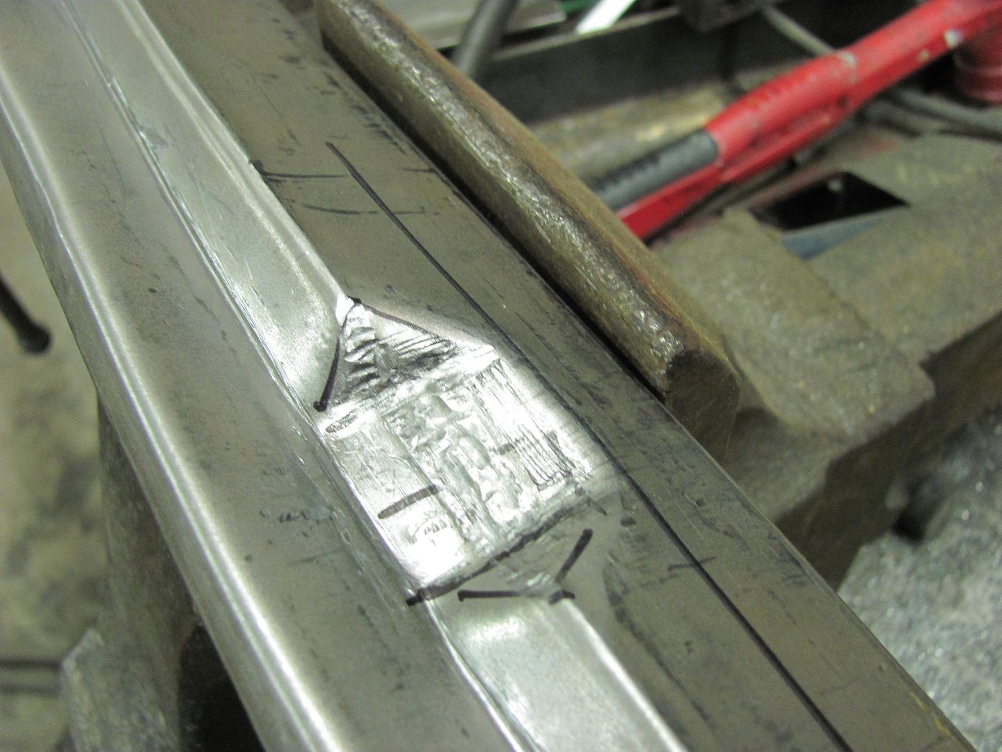
Here's the new "anvil", made from some phenolic sheet.....
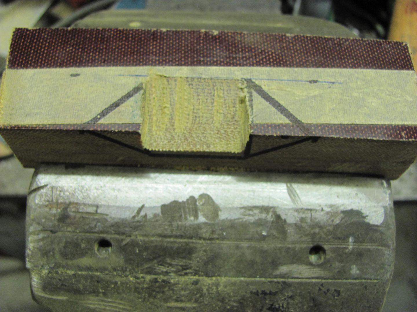
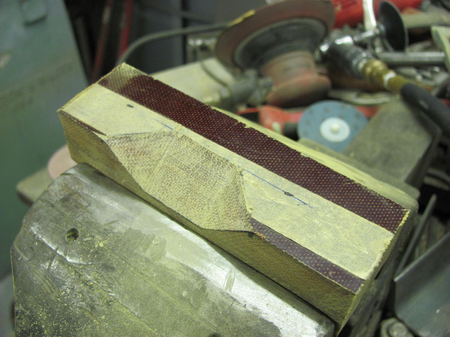
Put an alignment mark on the anvil, fitted it to the originals, and added the mark there as well. Then transposed those marks to the new piece...
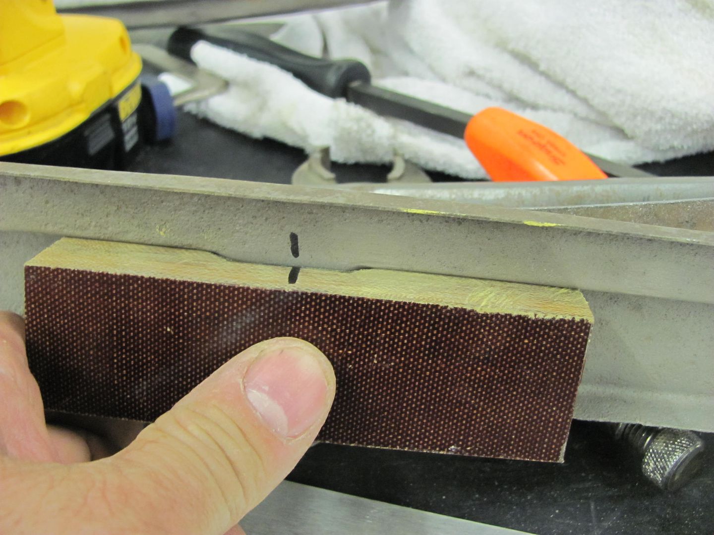
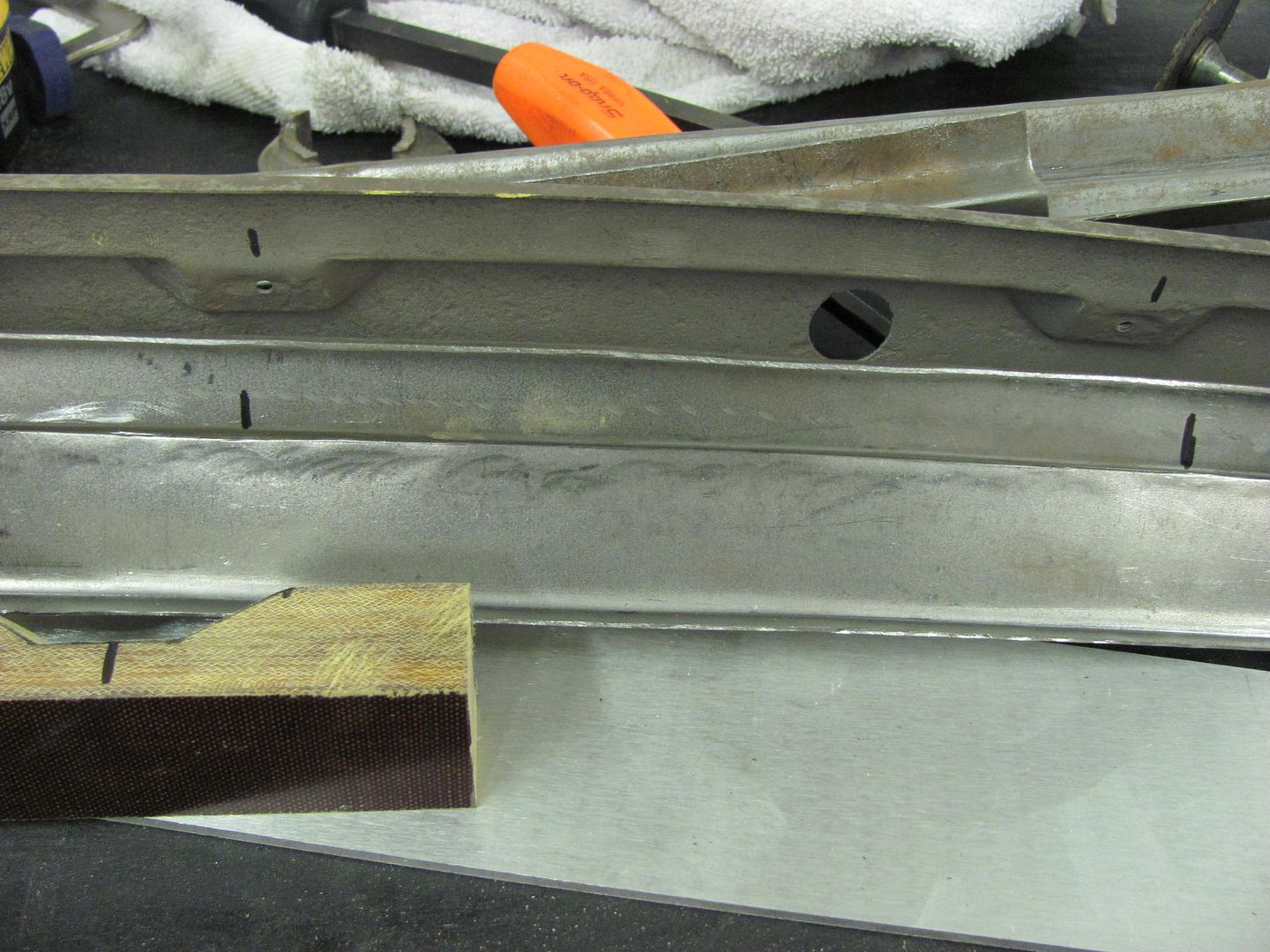
Anvil was located, and clamped in the vise to hold it's location
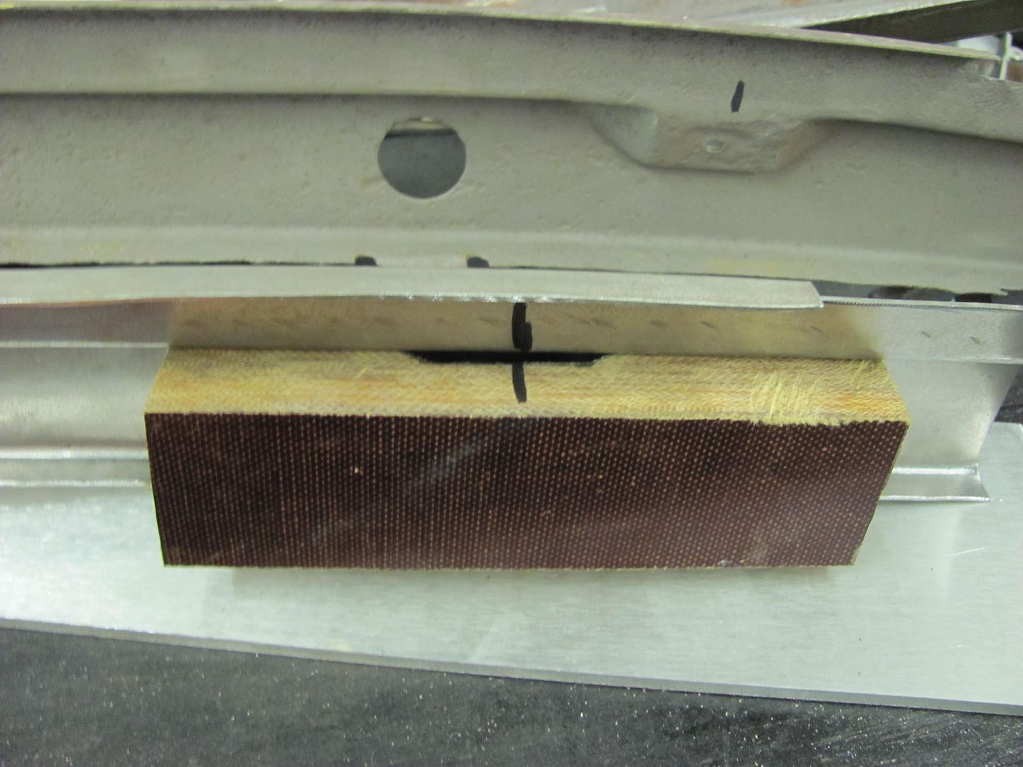
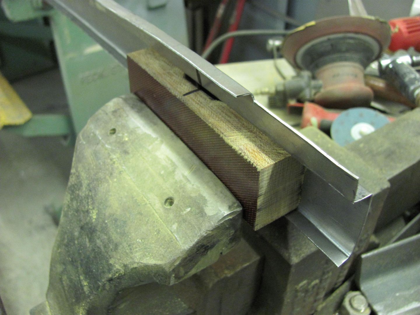
Started with the barrel end hammer.....
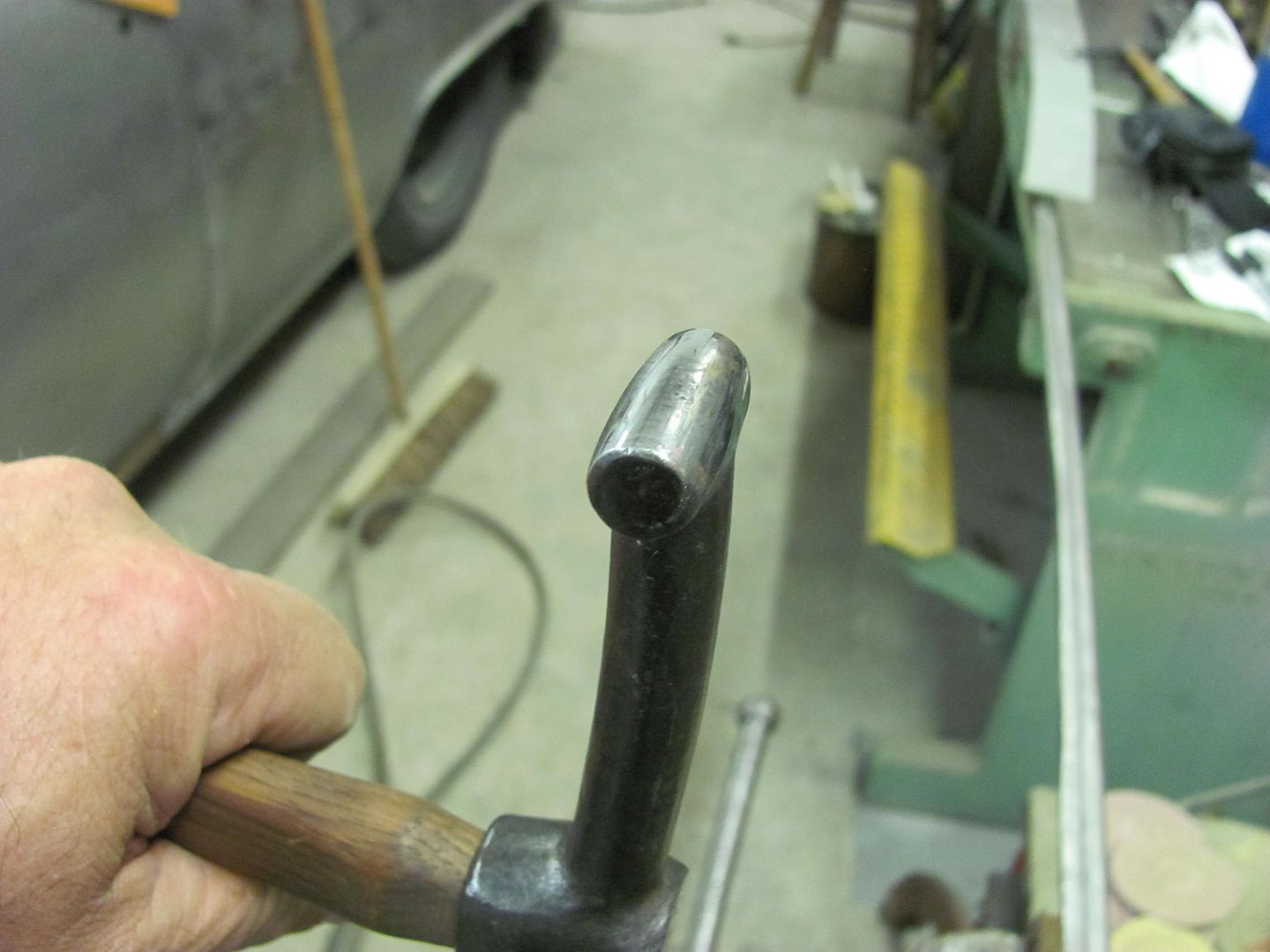
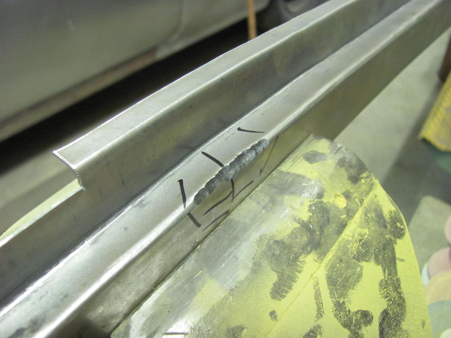
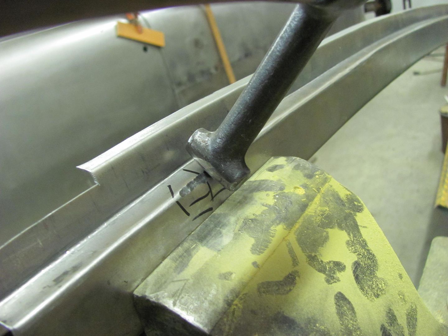
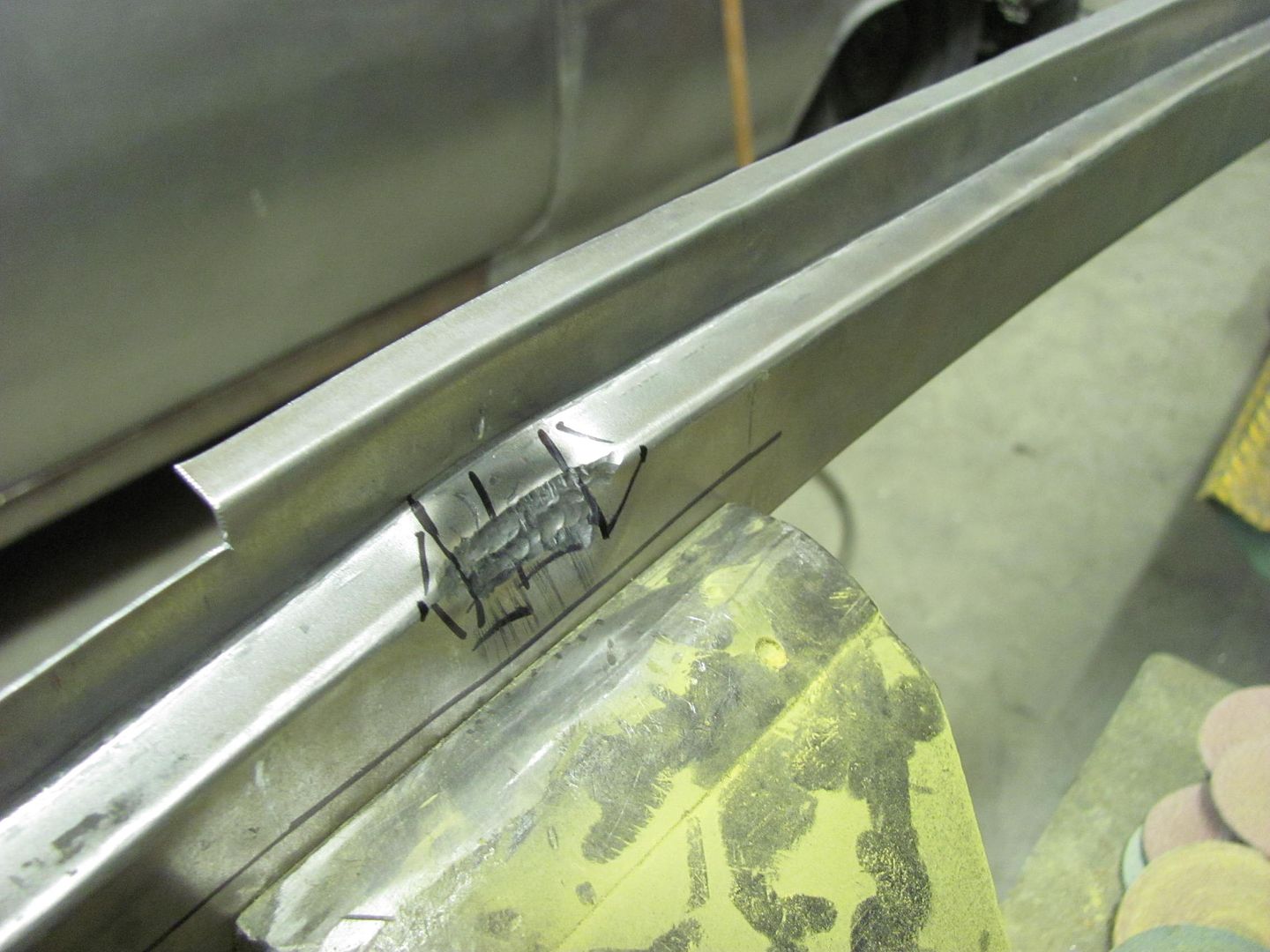
For the ends, I used a rounded tip chisel....
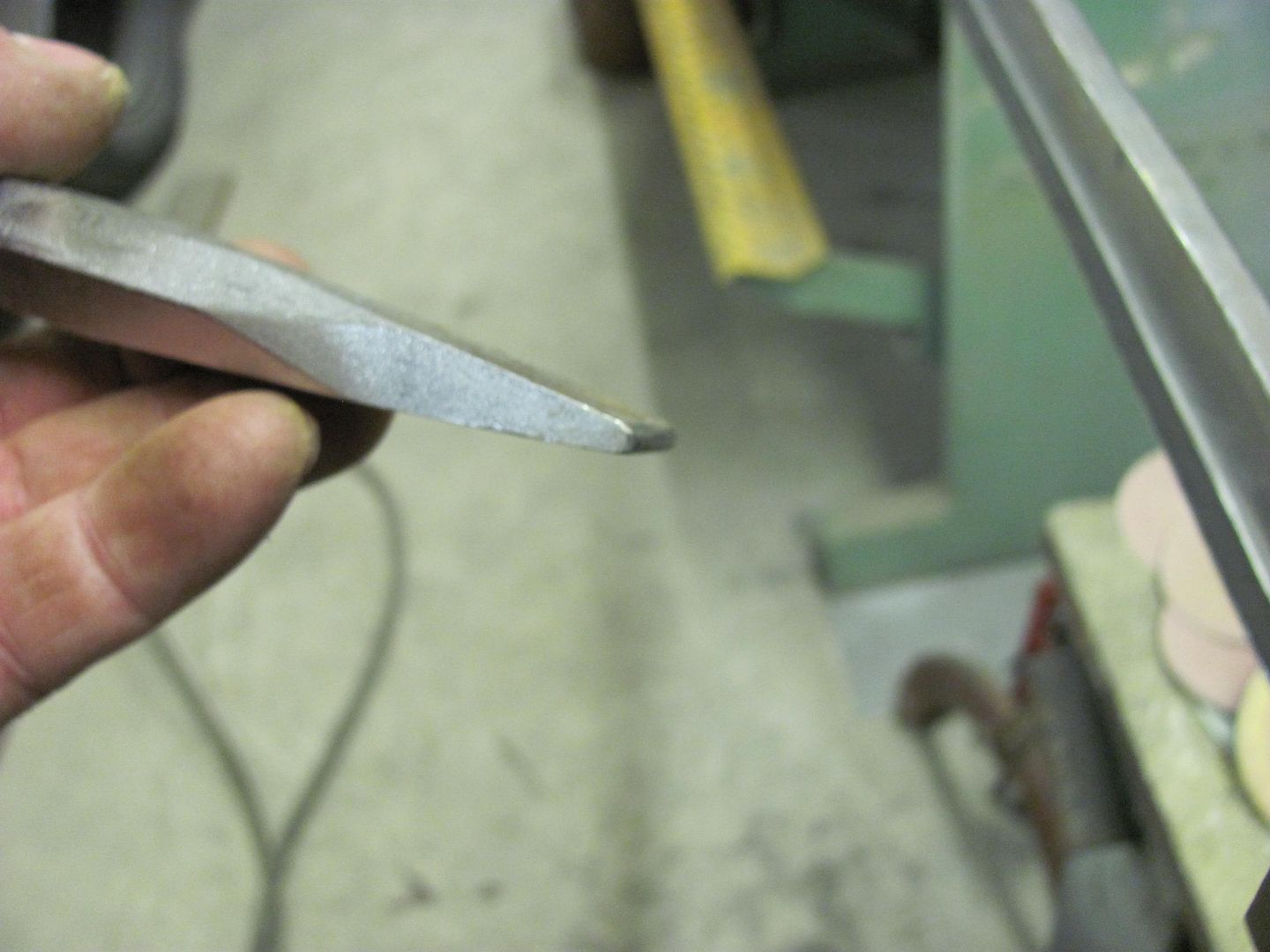
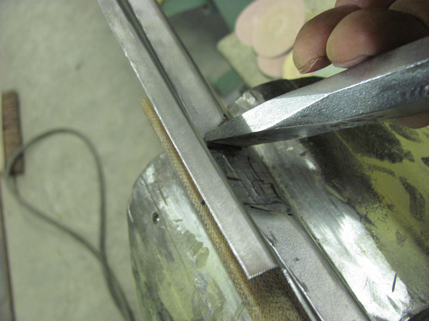
....and then another "anvil" to clean up the hammer marks a bit...
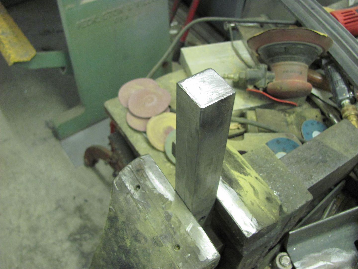
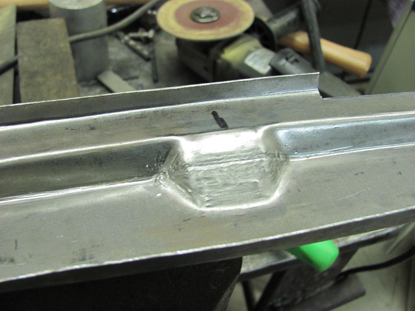
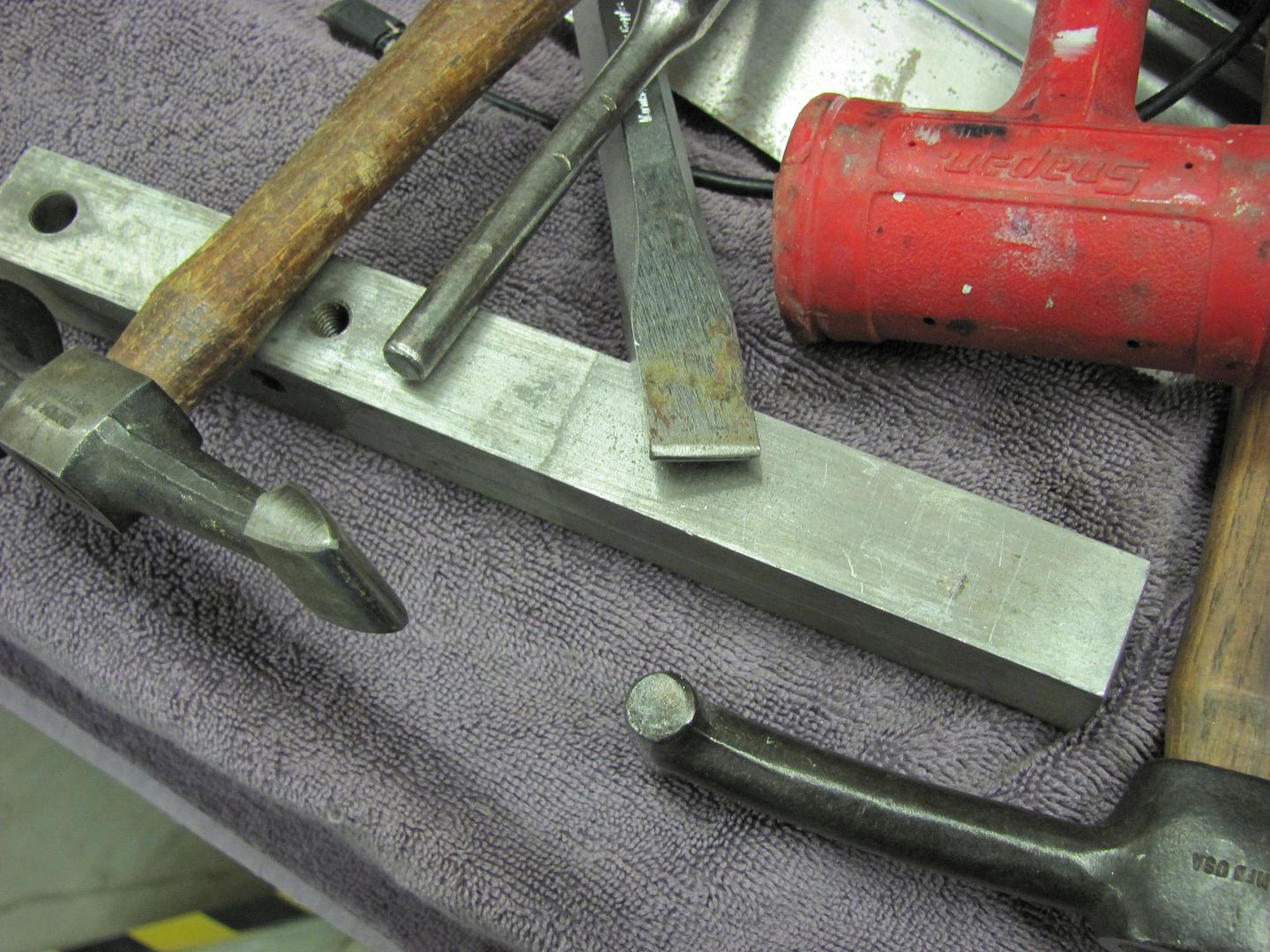
Here's all the tools used....
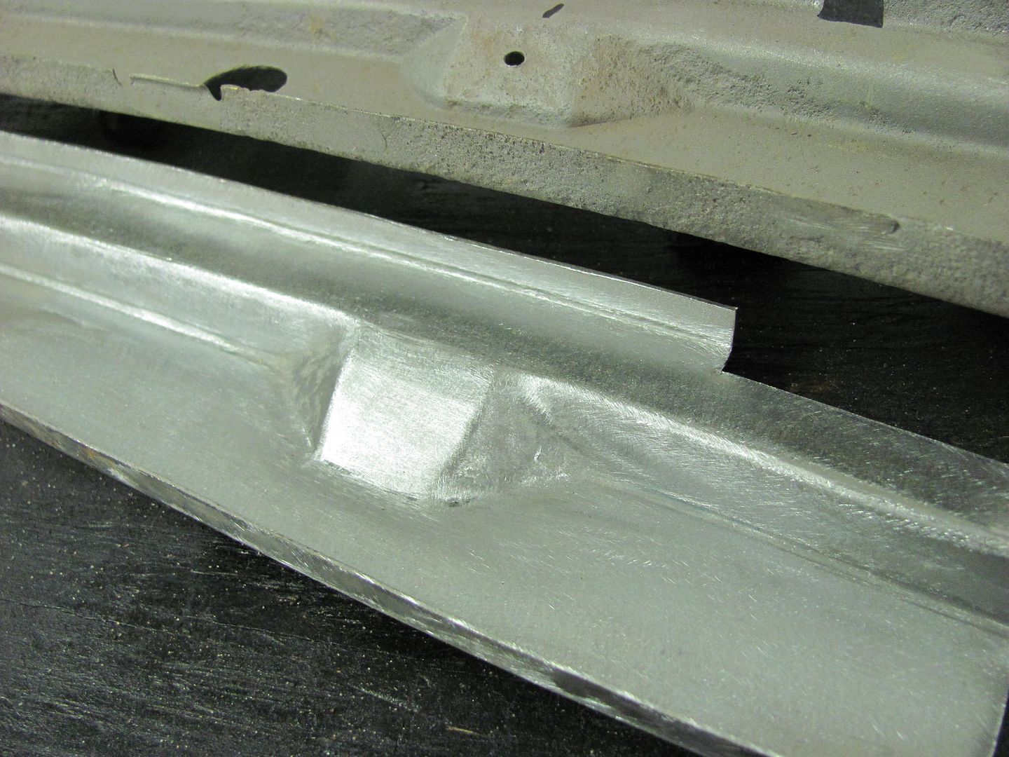
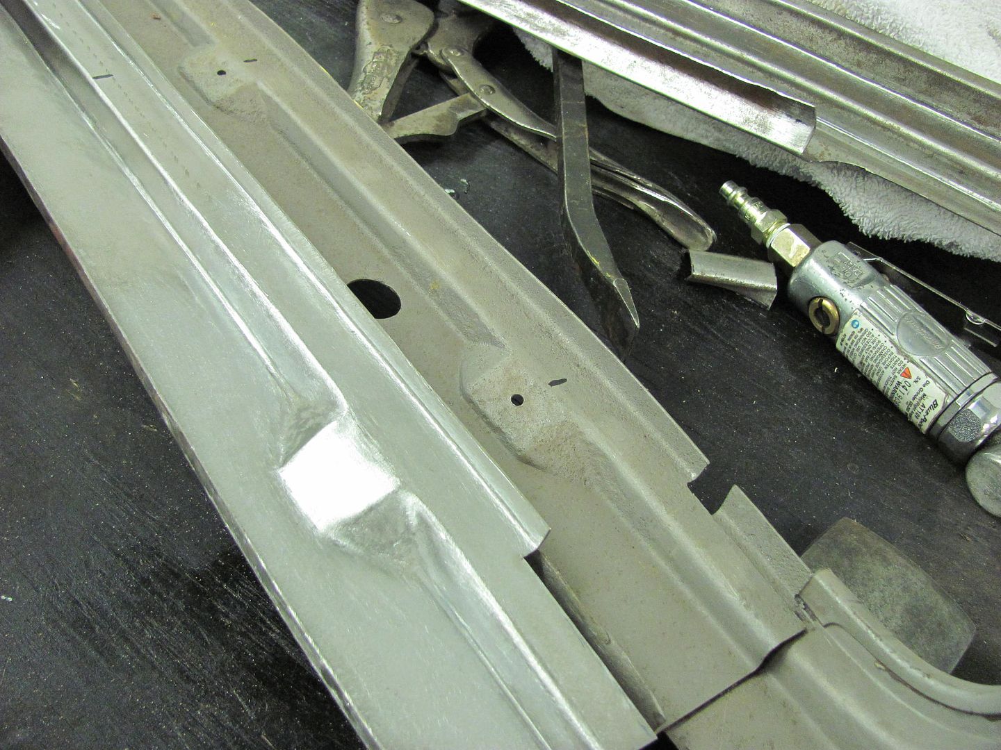
Touched up a bit with a sanding disc, looks close enough.... One down, 4 to go...
Robert
-
10-13-2013 03:44 AM #95
Ingenious! Amazing! Fascinating! I love reading your posts.. I learn details that I've admittedly, just never thought of before!
So thanks for making the time to share!!
-
10-13-2013 06:53 AM #96
Ditto Mike's comment. Thanks for taking time to post such detailed info on how you're working the metal. It's an education every time you post!Roger
Enjoy the little things in life, and you may look back one day and realize that they were really the BIG things.
-
10-14-2013 08:26 PM #97
Love the way ya do that stuff,I know I'd just weld a tab on,but some day some one may wounder if that was a stock part vs my way they'd know it wasn't,great work
-
10-17-2013 06:41 AM #98
Thanks for the comments guys, hopefully some of the processes shown will help someone to tackle some metalwork of their own.
Last night I worked to finish up the pad details on the inner structure of the lift gate.... The center one was wider, so I used the same phenolic and just added a wider detail to the opposite side. I missed showing this earlier, but a handy-dandy battery saw works well to remove the bulk of the material, sawing parallel cuts and then just working the saw side to side to clear out the remaining....
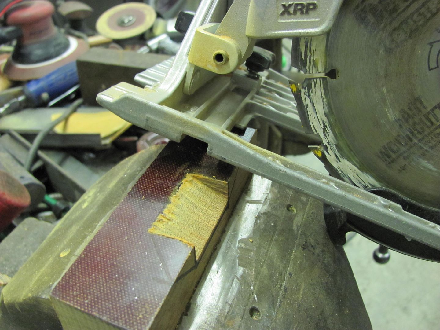
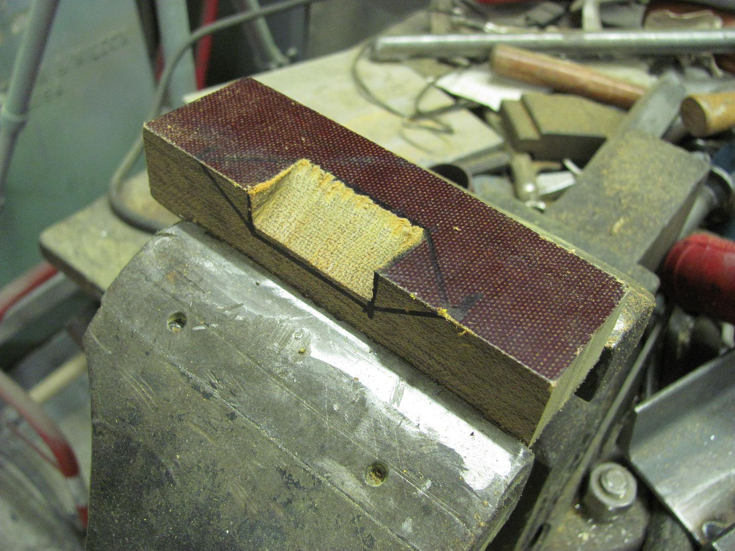
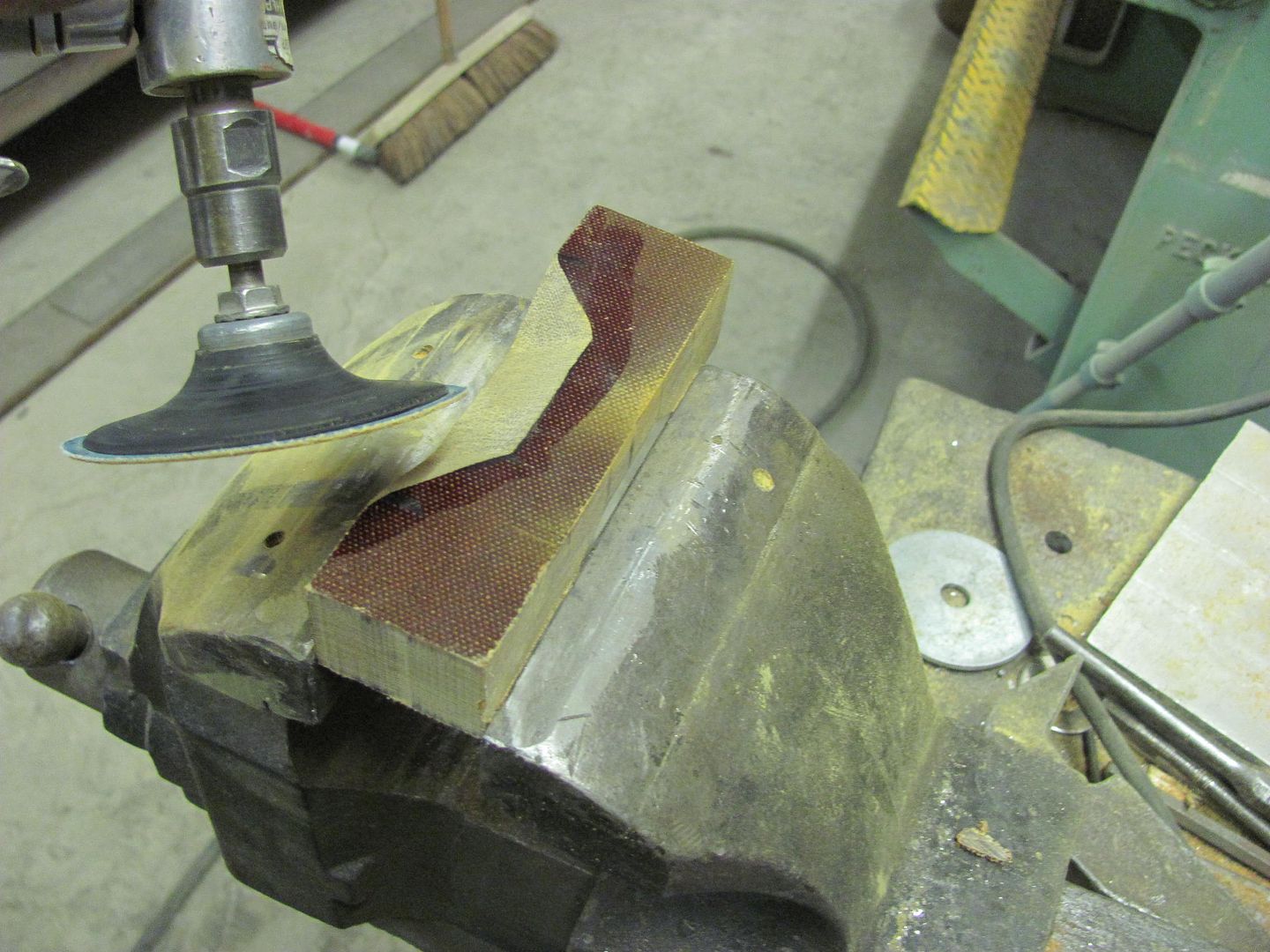
Once cut out, the sanding disc is used to cut down the angled sides and touch up the bottom..
This compares the two, showing the difference in width...
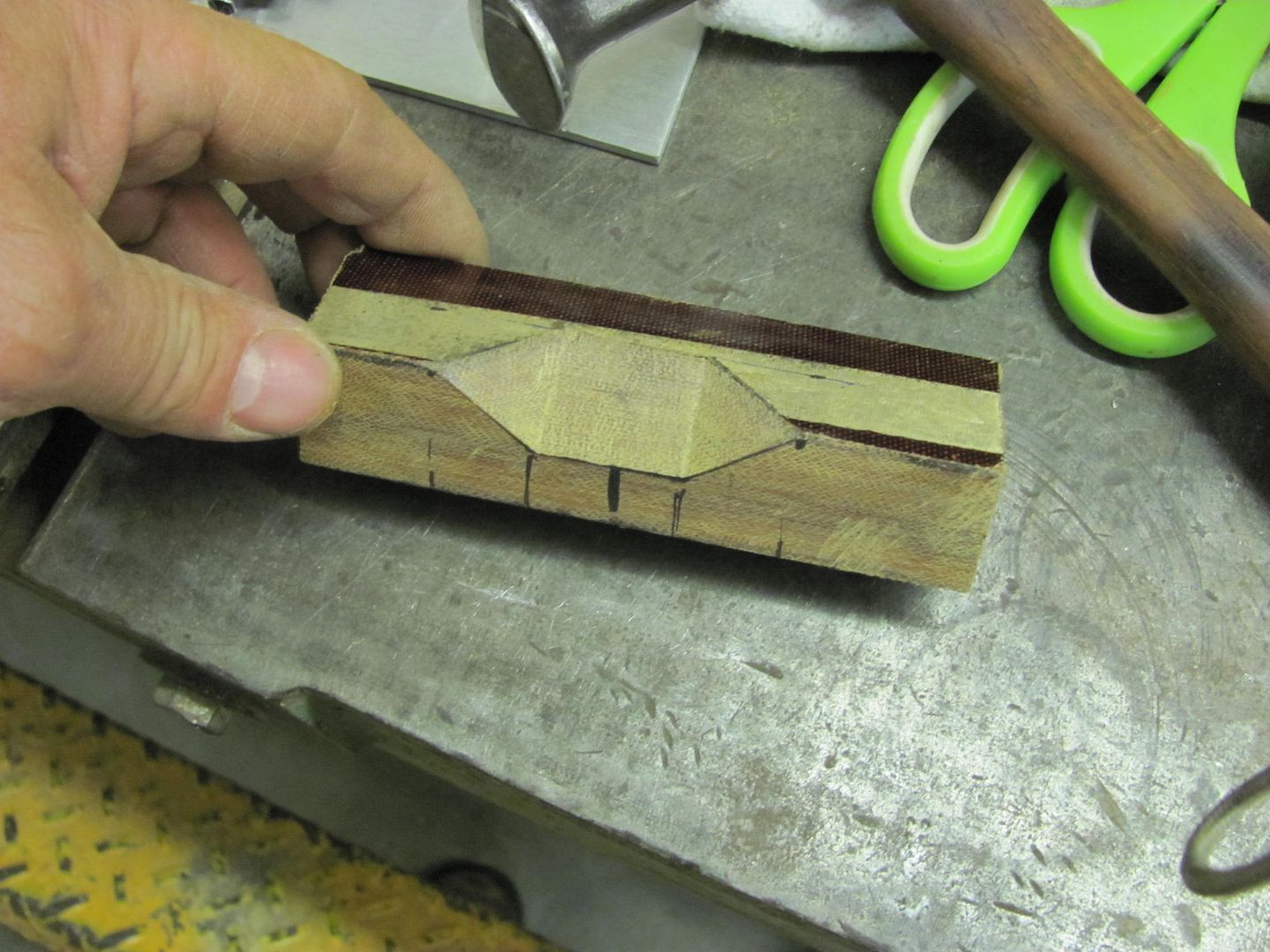
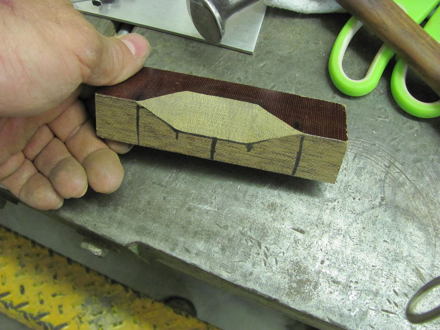
Alignment marks transposed from the original, and guide marks indicate the area in need of hammering...
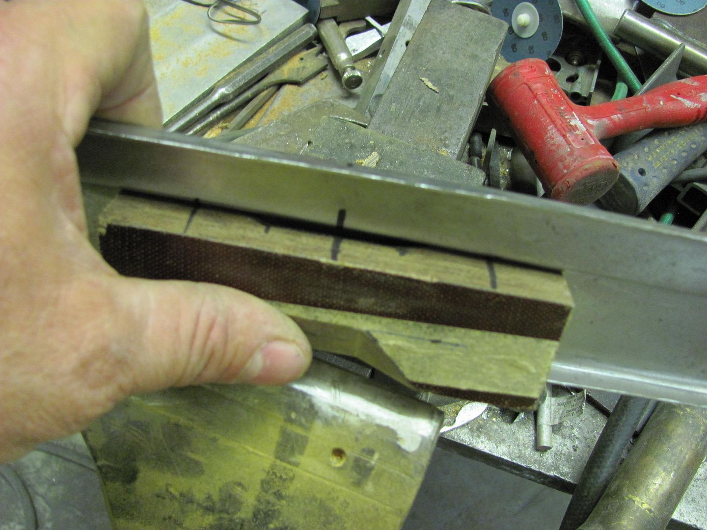
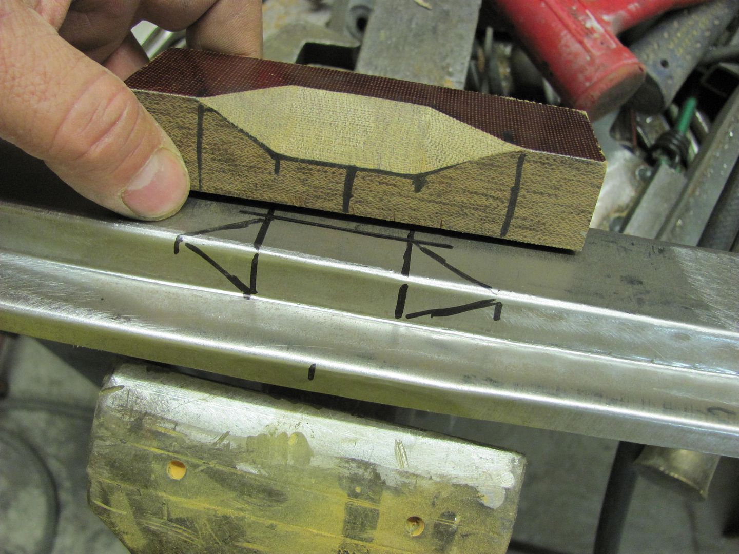
I had a request to show the hammering procedure, so here's another video attempt. The first one is using the phenolic anvil clamped against the work piece in the vise, the second uses 1" square stock as an anvil to clean up the hammer marks a bit...
Video232.mp4 Video by rmccartney | Photobucket
Video233.mp4 Video by rmccartney | Photobucket
...also sounds like I have a loose hammer handle, something for another day....
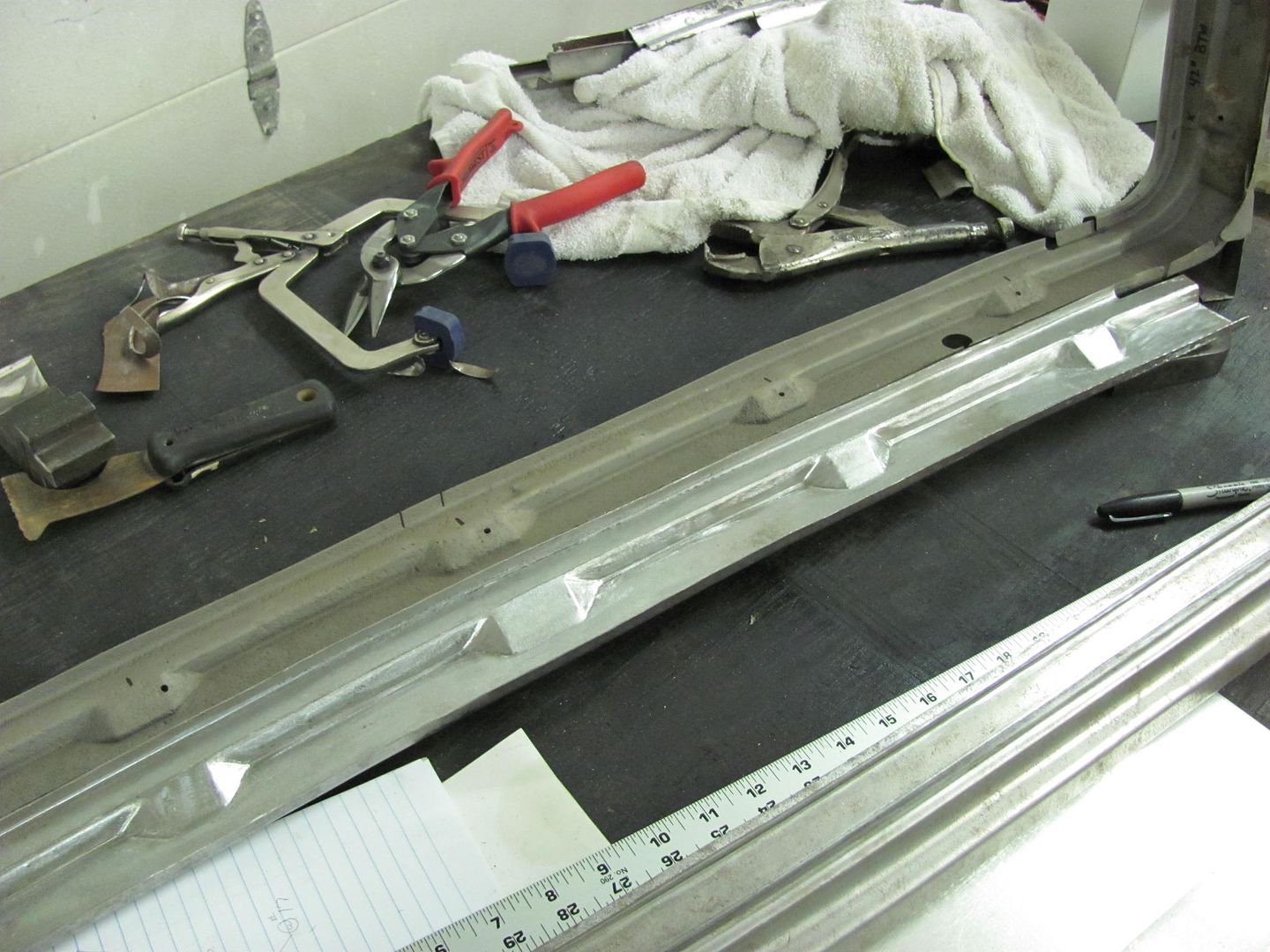
Then the sanding disc was used for final cleanup. Here's the finished piece, just needs a couple holes drilled....

Robert
-
10-17-2013 04:19 PM #99
- Join Date
- Apr 2011
- Location
- Prairie City
- Car Year, Make, Model: 40 Ford Deluxe, 68 Corvette, 72&76 K30
- Posts
- 7,301
- Blog Entries
- 1
Wow, such great work! I really like the modification you did to the vice grips to make the lip puller/spreader. Thanks for sharing this stuff! I'd really like to gather a collection of metal working tools like you have. Very nice!Ryan
1940 Ford Deluxe Tudor 354 Hemi 46RH Electric Blue w/multi-color flames, Ford 9" Residing in multiple pieces
1968 Corvette Coupe 5.9 Cummins Drag Car 11.43@130mph No stall leaving the line with 1250 rpm's and poor 2.2 60'
1972 Chevy K30 Longhorn P-pumped 24v Compound Turbos 47RH Just another money pit
1971 Camaro RS 5.3 BTR Stage 3 cam, SuperT10
Tire Sizes
-
10-24-2013 08:43 PM #100
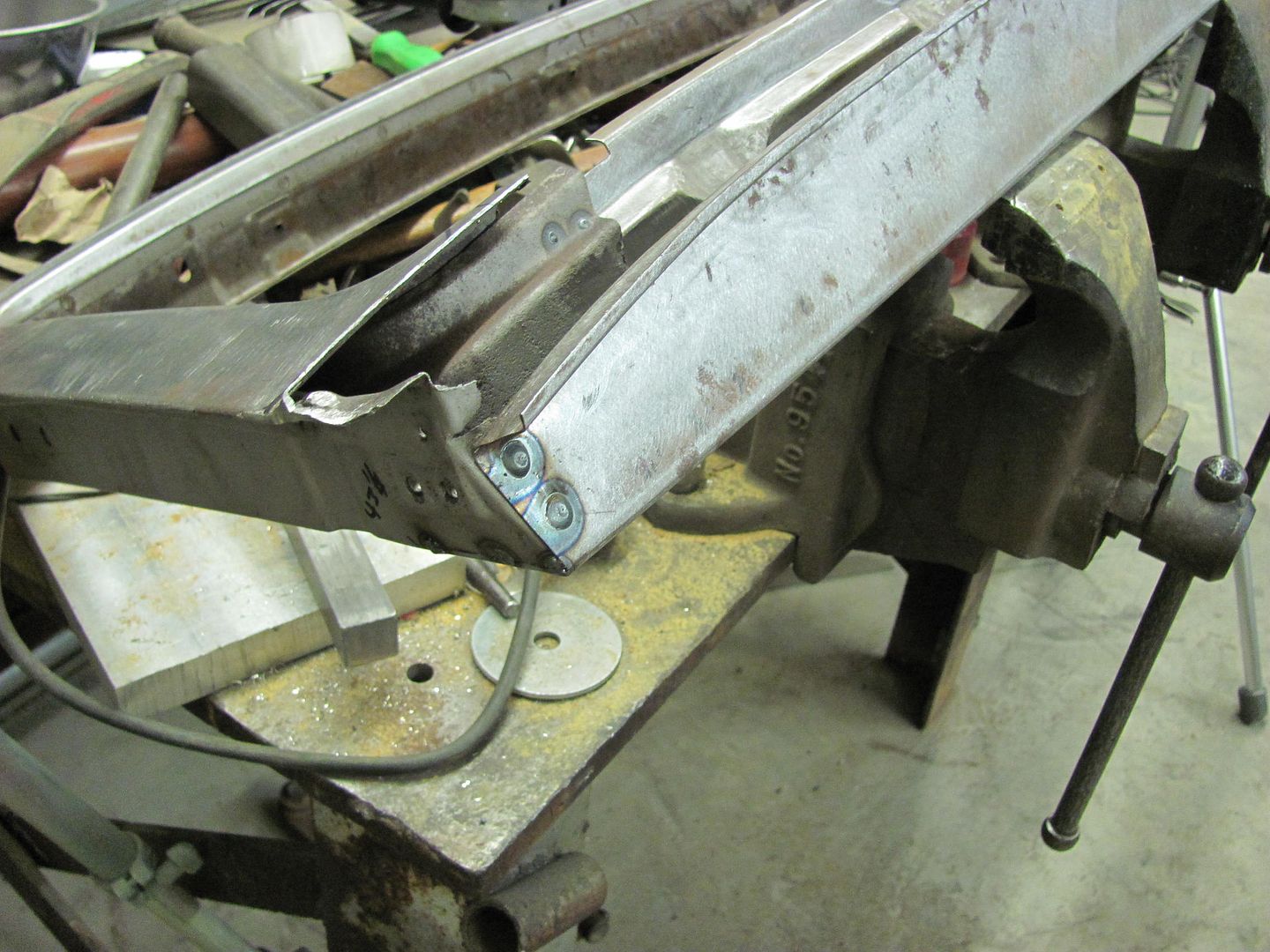
Thanks! Back to the lift gate, the spot welds in the bottom piece were drilled out. This revealed a couple more pits, which were media blasted and MIG welded.
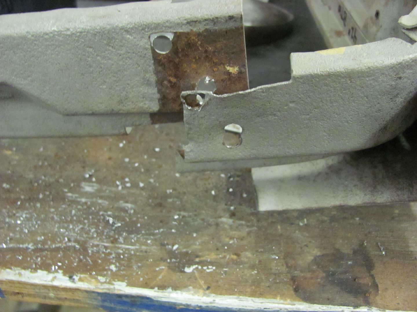
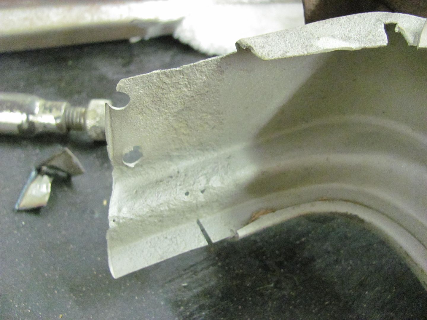
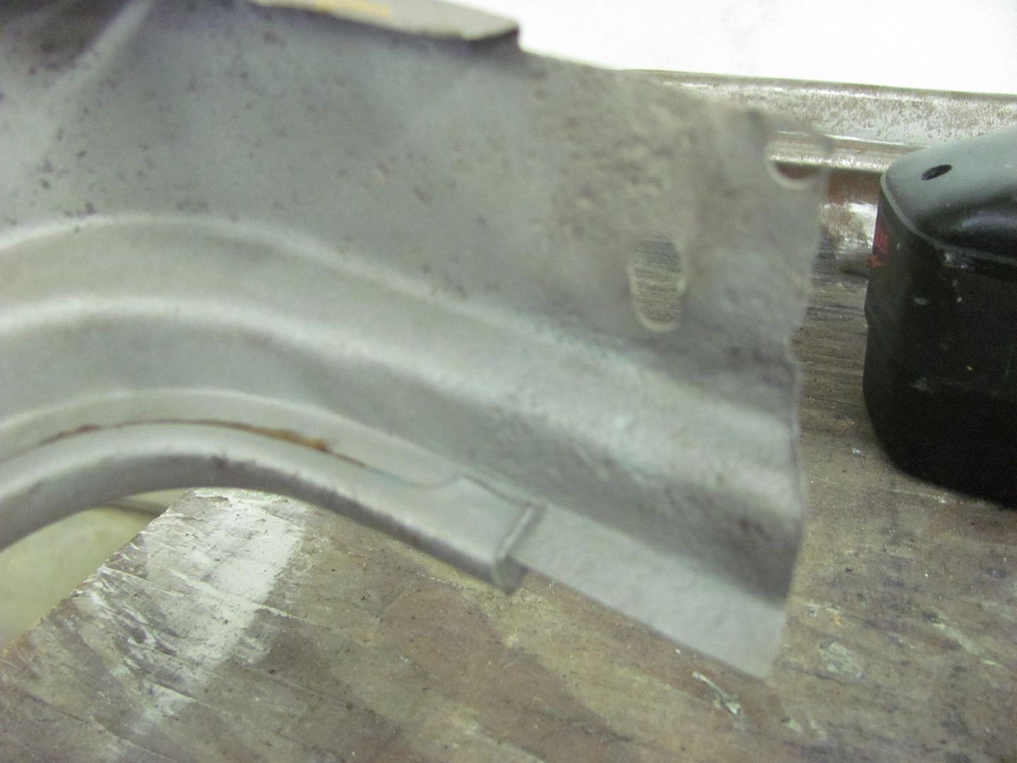
All cleaned up, the new piece is plug welded on....
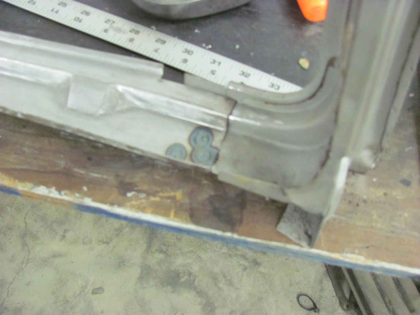

Then the inner panel is fitted up and tacked in place....
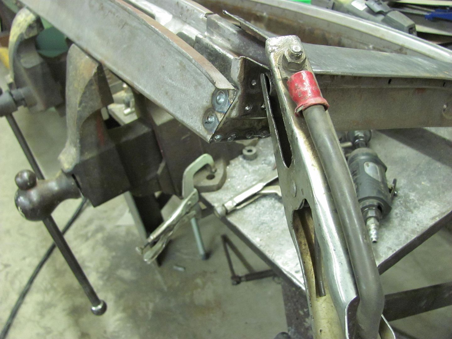
Top flange clamped to check the fit.....
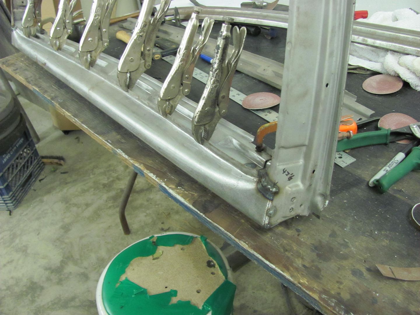
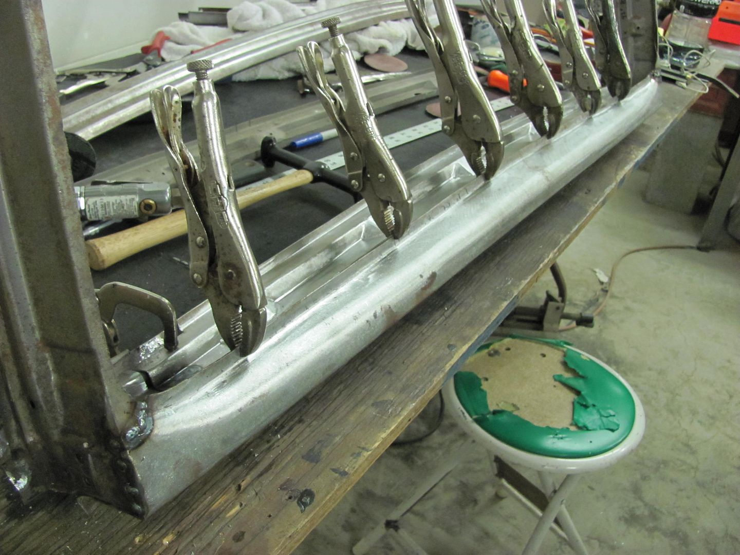
That's about it until next time...Robert
-
10-25-2013 02:28 PM #101
- Join Date
- Apr 2011
- Location
- Prairie City
- Car Year, Make, Model: 40 Ford Deluxe, 68 Corvette, 72&76 K30
- Posts
- 7,301
- Blog Entries
- 1
Looking real nice!Ryan
1940 Ford Deluxe Tudor 354 Hemi 46RH Electric Blue w/multi-color flames, Ford 9" Residing in multiple pieces
1968 Corvette Coupe 5.9 Cummins Drag Car 11.43@130mph No stall leaving the line with 1250 rpm's and poor 2.2 60'
1972 Chevy K30 Longhorn P-pumped 24v Compound Turbos 47RH Just another money pit
1971 Camaro RS 5.3 BTR Stage 3 cam, SuperT10
Tire Sizes
-
10-26-2013 03:14 PM #102
Thanks!
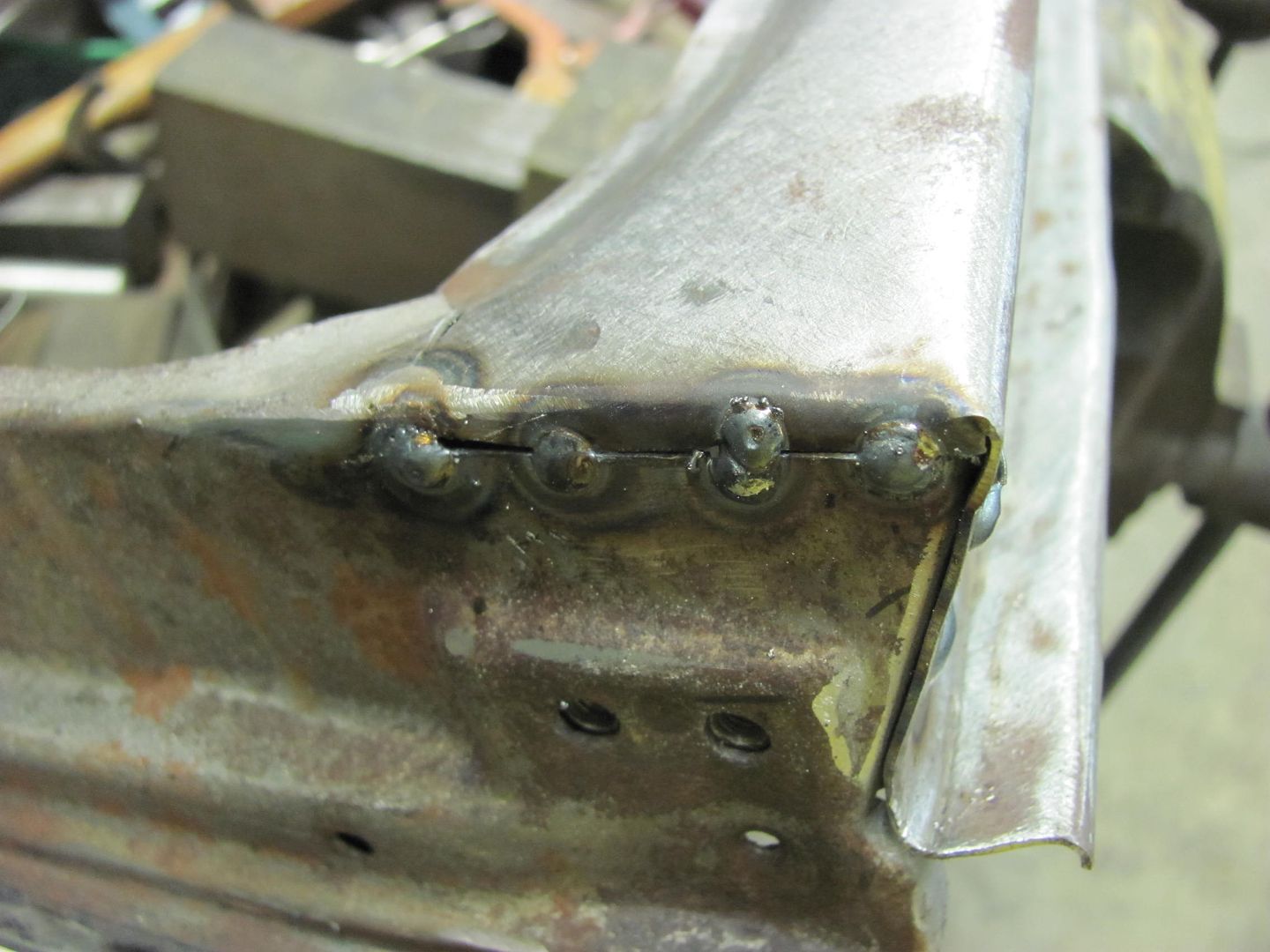
Finishing up the welding of the inner bottom panel....used a 3/16 hole for the plug welds this time. I normally use a letter A, but the flange here is a bit narrow, so a smaller hole it is. To make up for it the heat on the welder was cranked up a bit to insure a good weld.
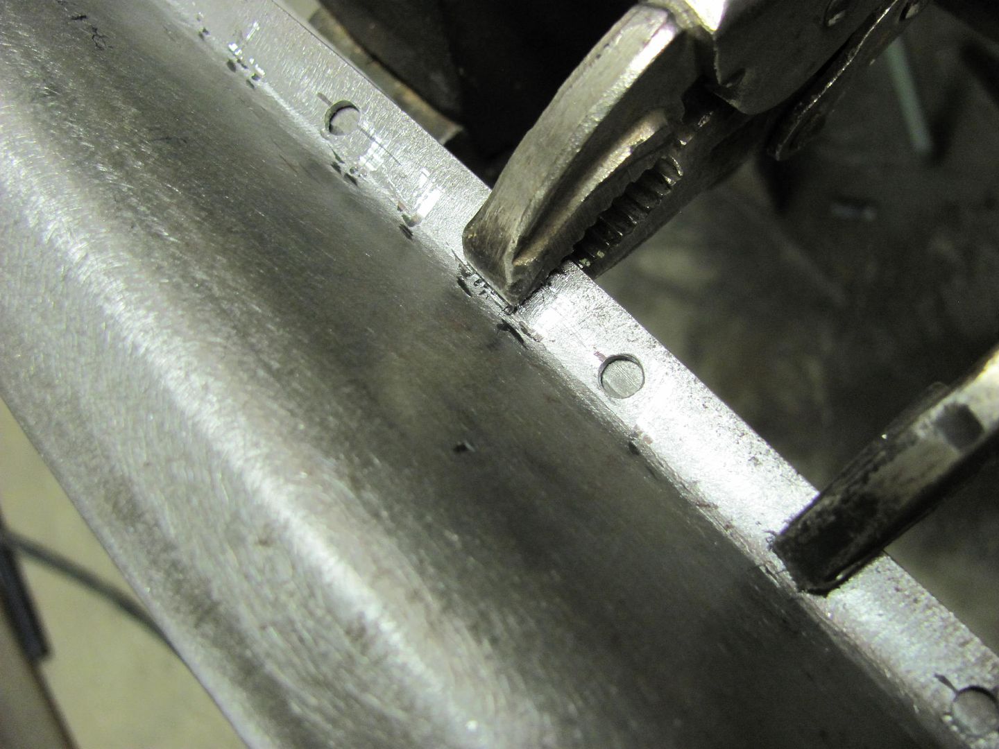
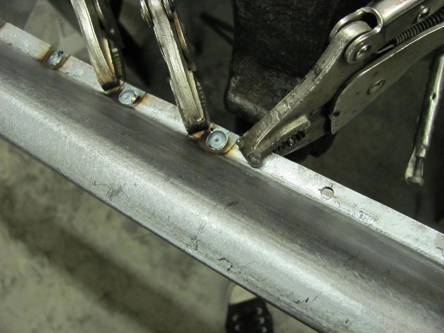
Looking at the back side, these should hold well.
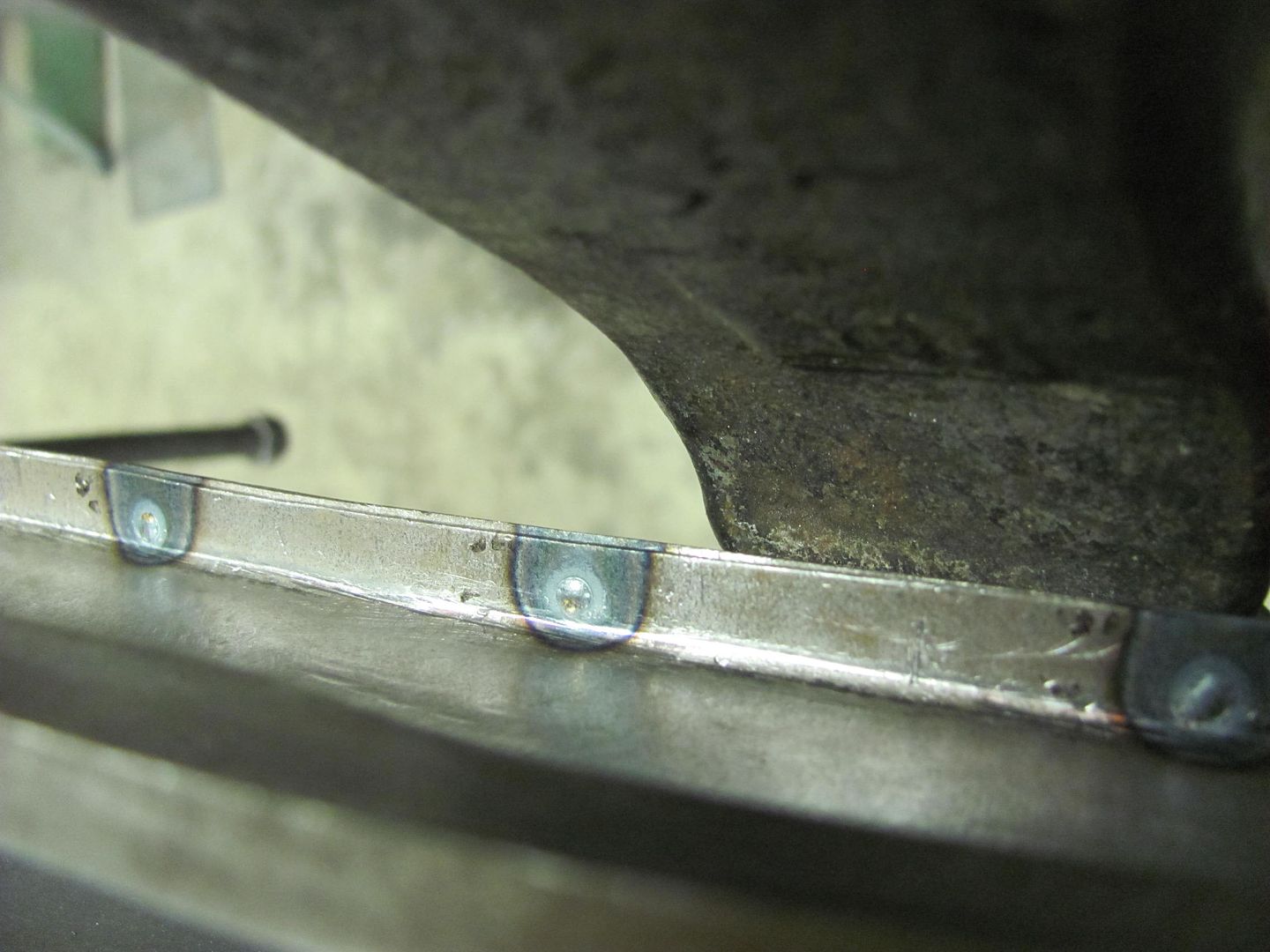
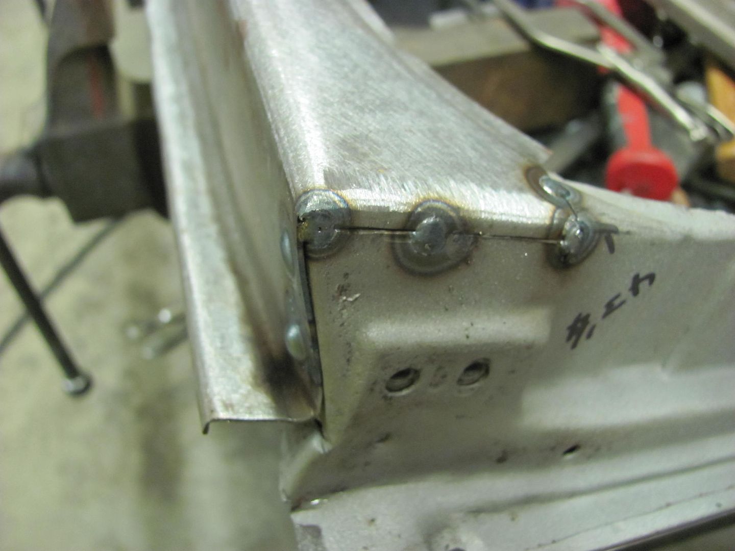
All the plug welds done, then on to the corner seams.....
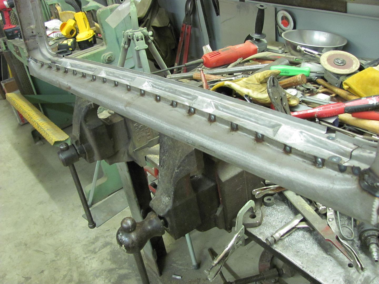
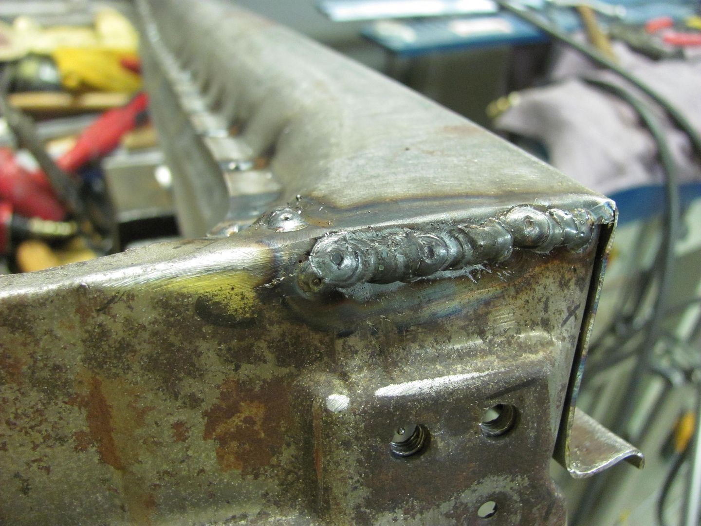
and after cleaning up the welds.....
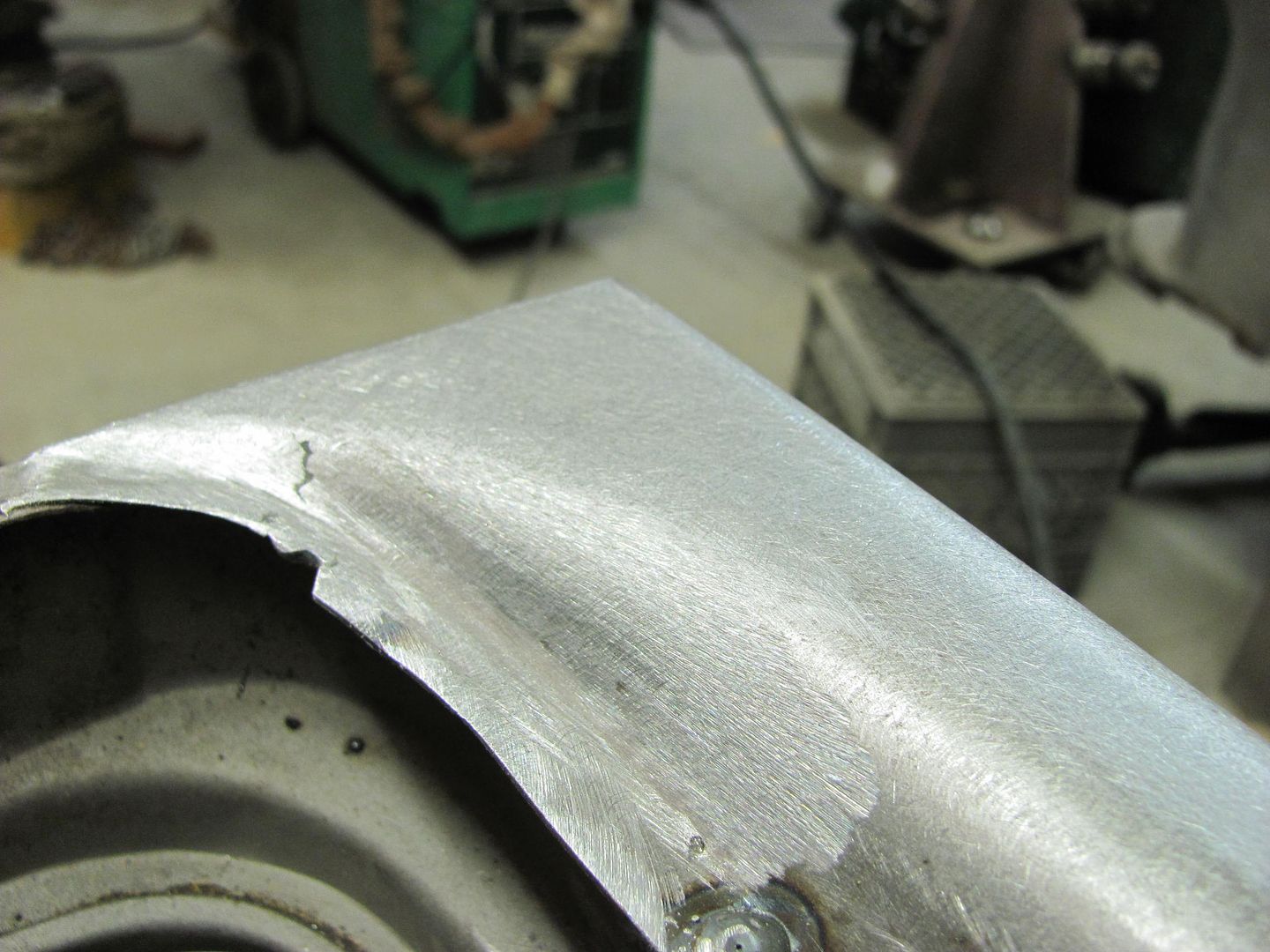
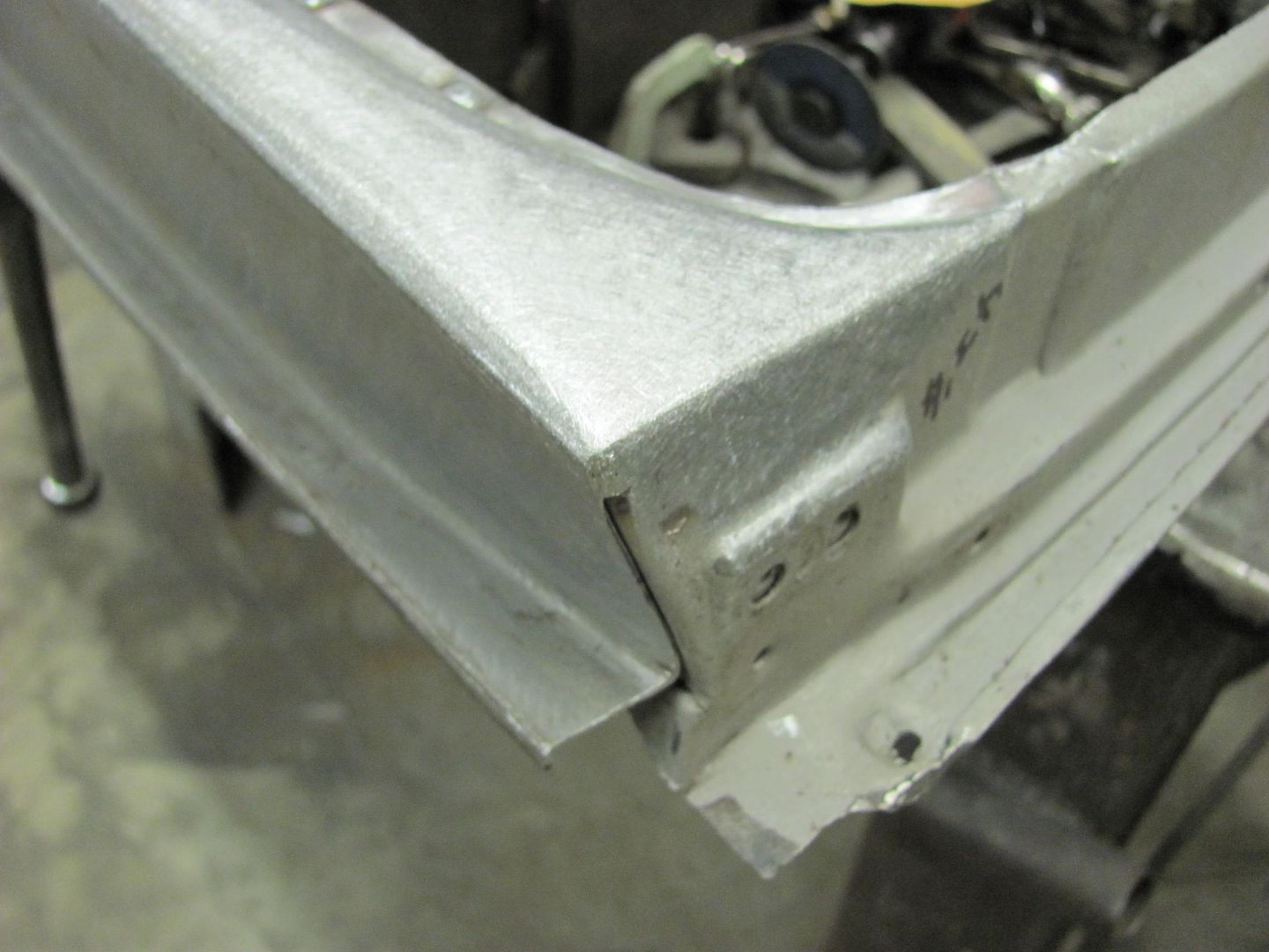
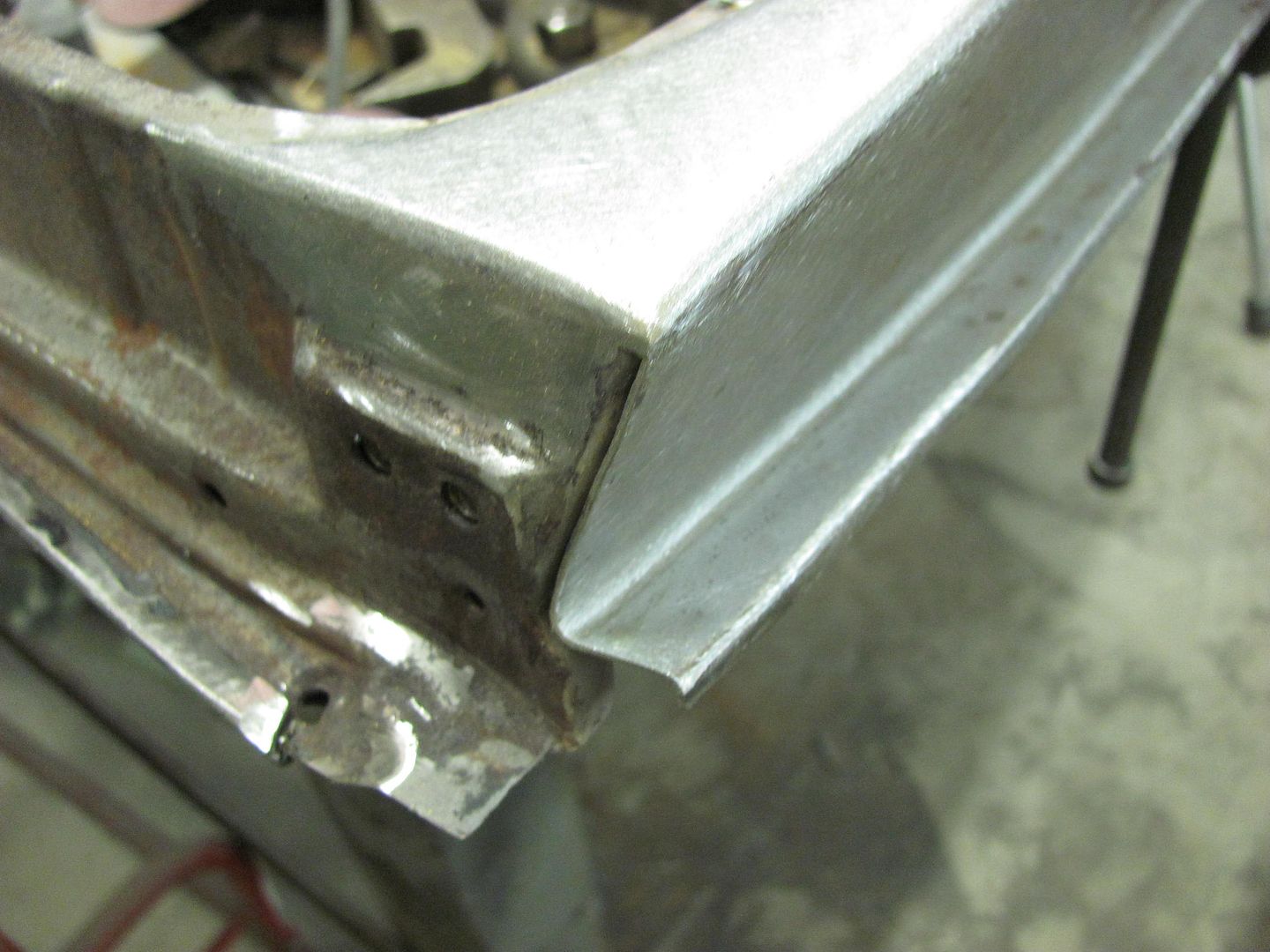


Then we'll clean up the plug welds on the flange, media blast the inside for good paint adhesion and some epoxy primer before closing it up..Robert
-
10-26-2013 03:33 PM #103
Wow mate, that is beautiful work you are doing, very impressive and encouraging. I noticed you don't use a zinc weld thru primer on the surfaces to be welded before assembly, is there a reason why you don't as I would of thought after all the work you put into manufacturing replacement panels you would want to take that extra precaution against the rusty nuts setting in again.
I maybe a little crazy but it stops me going insane.
Isaiah 48: 17,18.
Mark.
-
10-26-2013 08:29 PM #104
Thanks for the question. I am more of a proponent of epoxy over using weld through primers.. I typically will use epoxy between panels where weld through may be an option, and use a modified bit to clean out the plug weld hole:
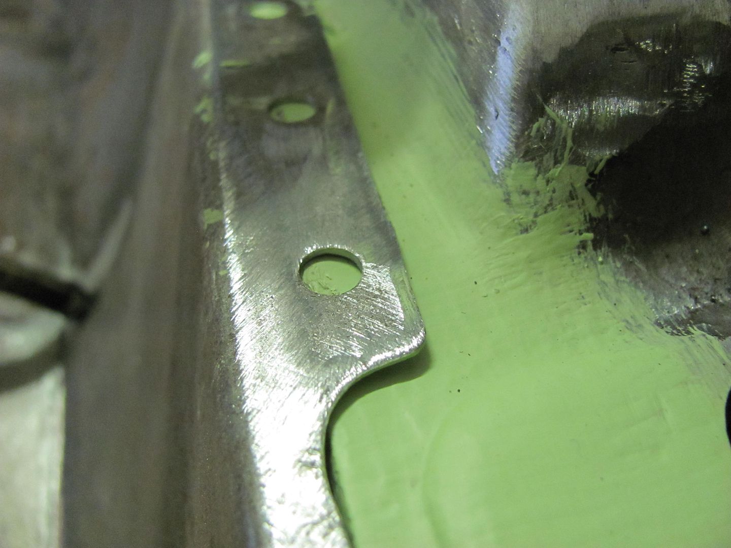
This is the same size drill bit I used for plug weld holes that has been flattened and backfaced with a roloc sanding disc to resemble an end mill cutter.
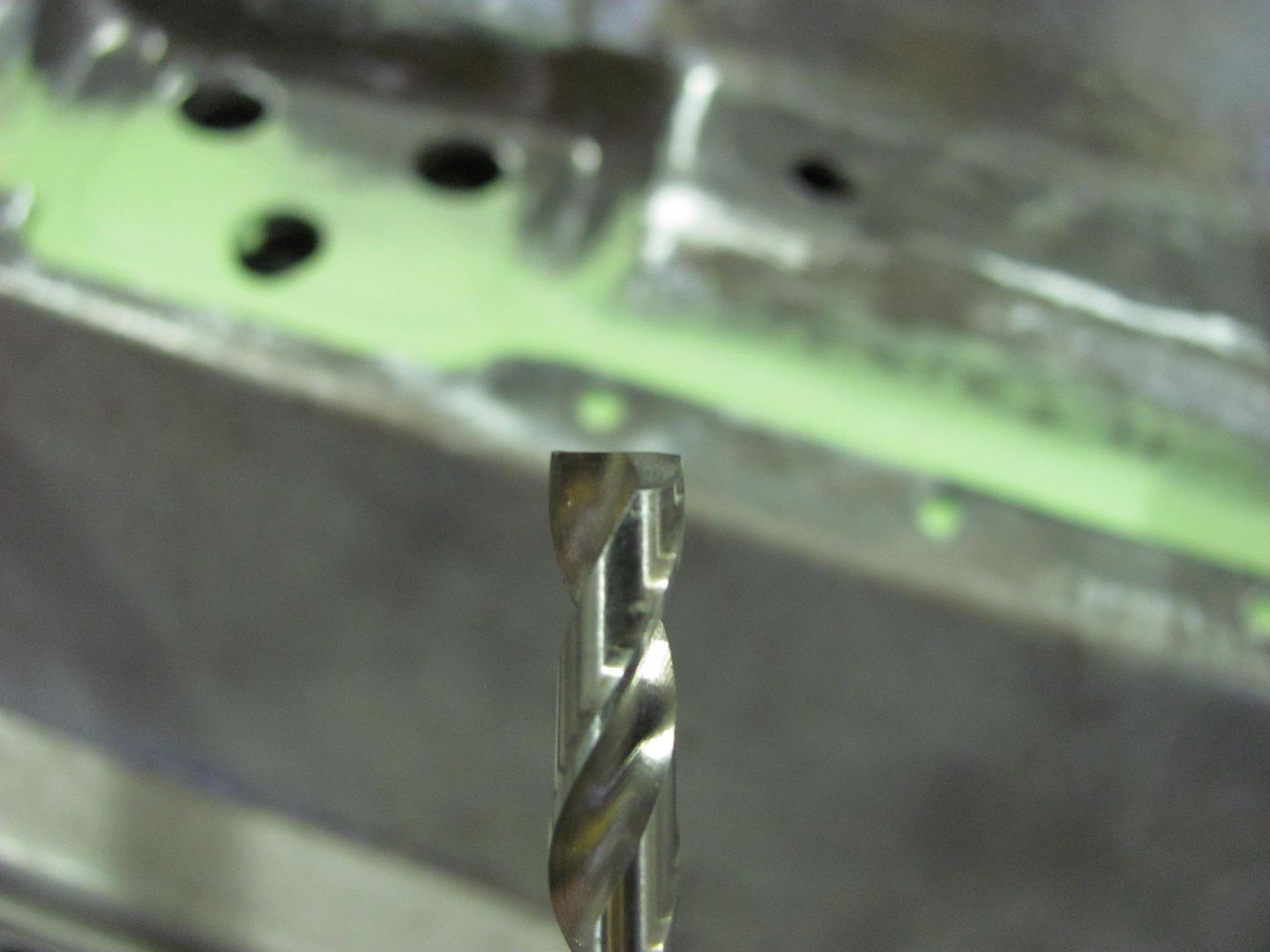
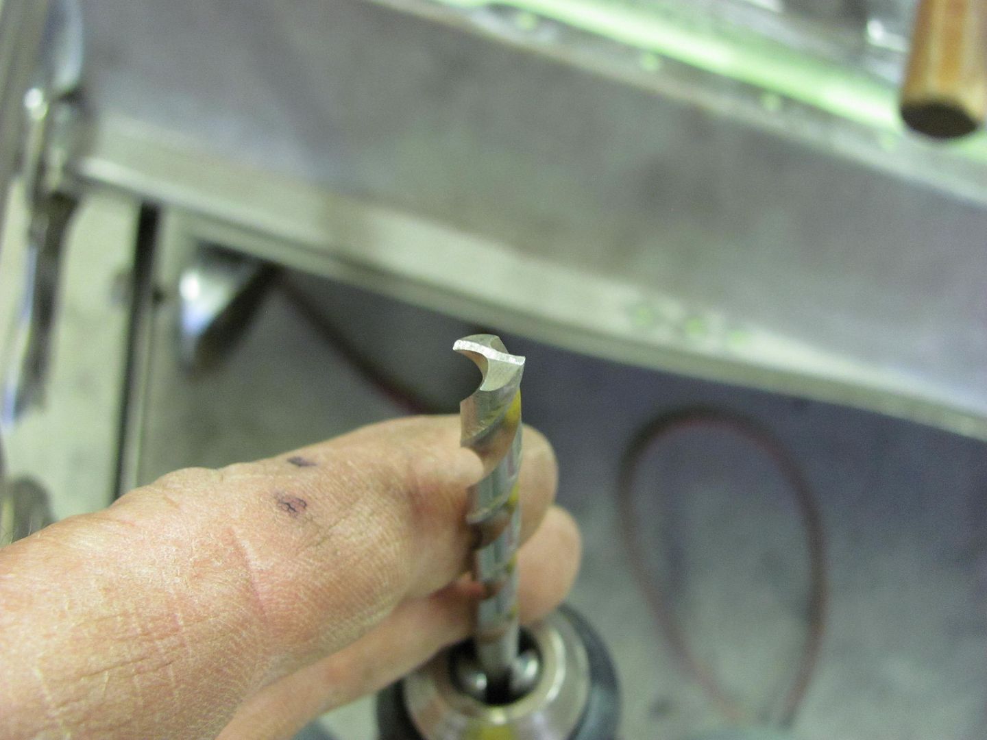
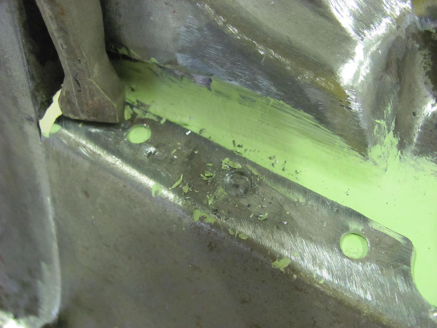
This shows how it works, cleans the paint from the metal surface, but having a flat face on the cutter, it doesn't affect the metal as a regular drill bit would. Notice most of the "chips" are paint....
And welded......
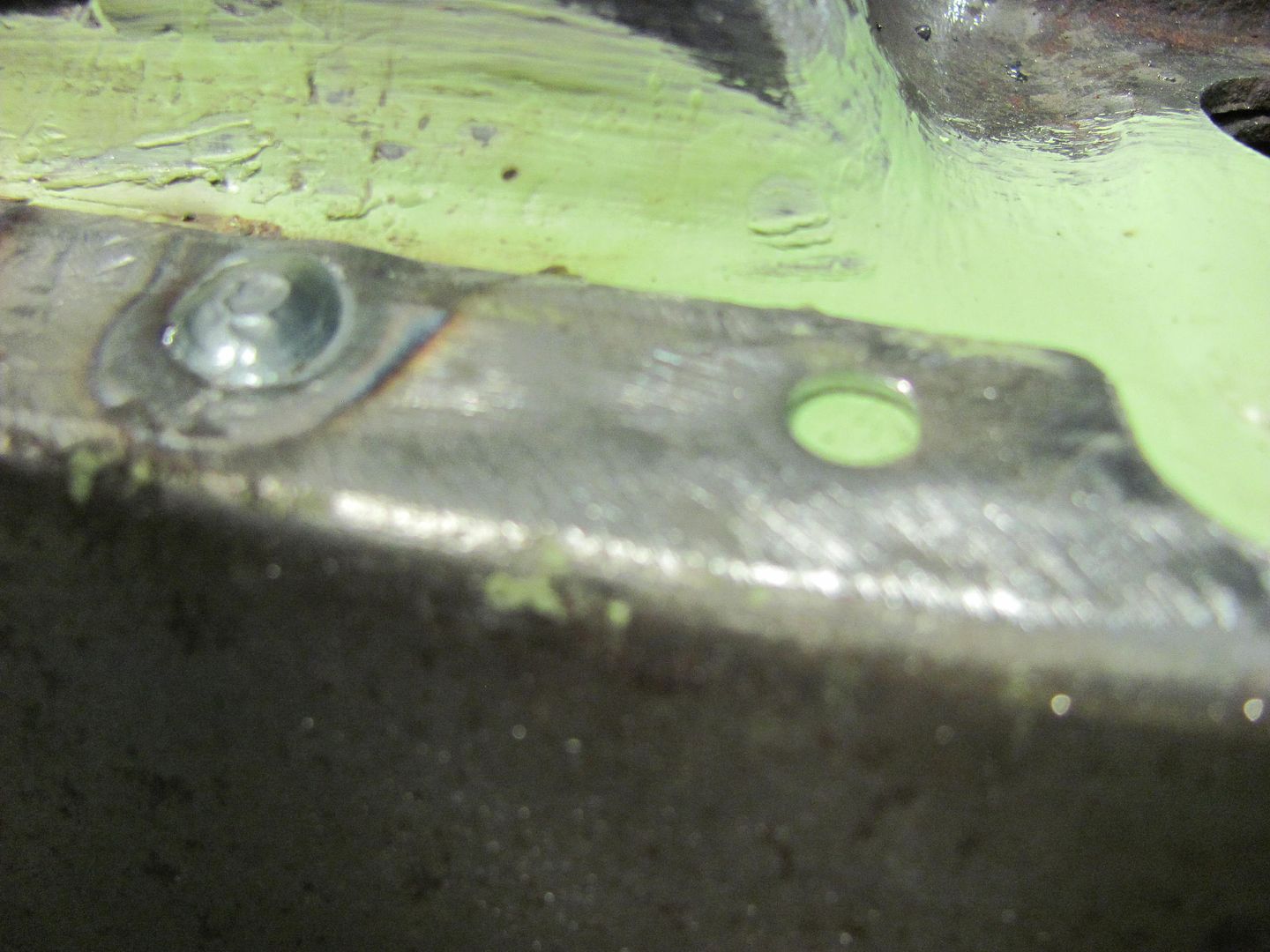
Where this pinch weld seam you referred to will be on top and less prone to water intrusion, it will be painted and sealed inside the cavity prior to welding the outside panel on. Where the lower seam will be more prone to water intrusion and rust, it will get some epoxy primer between the two panels prior to welding using the method shown in these last few pics....Robert
-
10-26-2013 09:53 PM #105
Good process and very little burn off when welding leaving a better seal between panel . I do it too .
.


 3390Likes

 LinkBack URL
 About LinkBacks
 Reply With Quote

Down all day yesterday, up today, shit or get off the pot.
Where is everybody?