Thread: Project Sebring GT Spyder
-
10-12-2016 07:47 PM #106
Now that I had the components for my brake system, I actually had to make all this mess work together.
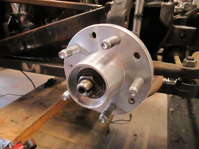
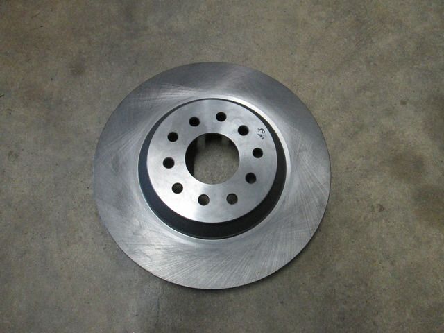
My first job was to drill the Corvette rotors to a 5 on 4 1/2" bolt pattern. The ECI hubs already had the studs pressed in on this BC. After drilling, the rotors slipped right on.
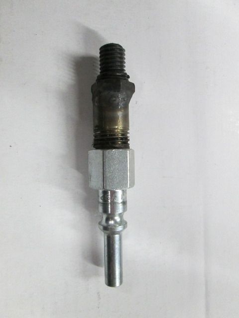
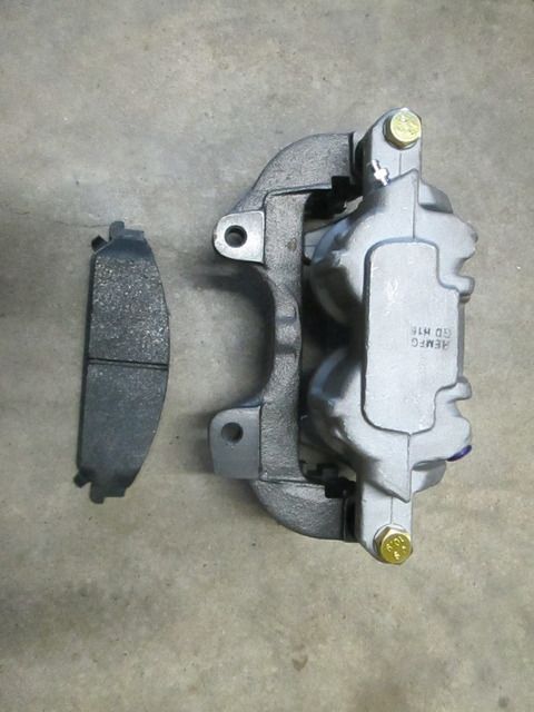
I started out on the front brackets by fabbing an air fitting that would screw into the hose port on the calipers. This allowed me to use the calipers own force to clamp it square to the rotor. This made getting the caliper positioned right and keeping where I wanted much easier. Turns out the Challenger pads were a perfect fit on the Corvette rotors. There was no wasted friction area.
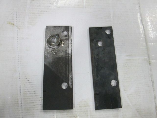
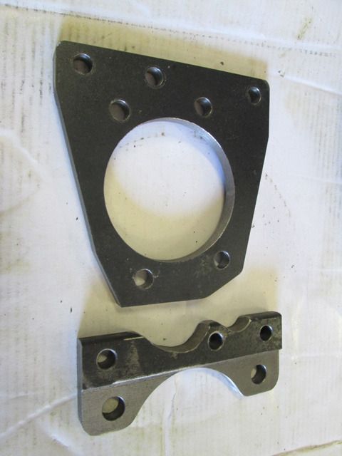
The next hurdle was getting all the bolt locations correct. Locating anything in 3 dimensions is never simple. The actual caliper mounting holes were on the same plane and easy to get. For the spindle hole, I made up a dummy plate with an oversize hole approximately where the bolt was to be located. I sandwiched a close fitting washer under the spindle bolt and positioned the bracket(with caliper) where I wanted it. I tack welded the washer to the dummy bracket and then located the holes on my mill using the x and y axis readouts. Once I had the locations, I made up another dummy bracket to make sure everything was where it needed to be.
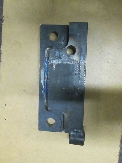
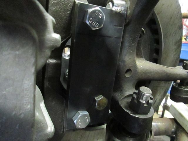
The actual brackets were fabbed from two pieces of 3/8" plate and have a threaded sleeve welded on for the second spindle bolt. The threaded sleeve actually sits in a small notch and butts against the main bracket. The weld isn't under much load. That part of the bracket is under compression loading under normal braking so the notch is taking most of the force.
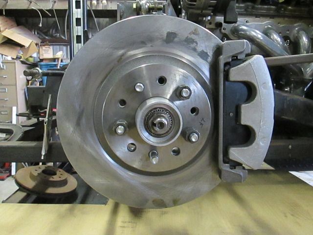
While I believe these fabricated brackets would hold up fine, I've decided to machine them from a solid piece of material. That 's a good winter job for a cold day when I don't feel like being in the unheated part of my shop. Now that I have the prototypes, making them from solid will be fairly easy (just time consuming). These will be good for the time being.
On to the rear brakes.
-
Advertising

- Google Adsense
- REGISTERED USERS DO NOT SEE THIS AD
-
10-12-2016 09:45 PM #107
Don't wish to digress from the theme of your thread; but couldn't let that remark go by without commenting on it:
A good friend of mine has a Sunbeam Tiger, I've been in it several times, but Ian has never allowed me to drive it. (Perhaps he doesn't trust me? I wonder why!)
I can vouch for the fact that they go like a scalded cat, and stick to the road like dogs**t to your shoe.
A real 'fun' car!
They're almost as much fun as the Cobra!
(...and Ian has never driven that!)johnboy
Mountain man. (Retired.)
Some mistakes are too much fun to be made only once.
I don't know everything about anything, and I don't know anything about lots of things.
'47 Ford sedan. 350 -- 350, Jaguar irs + ifs.
'49 Morris Minor. Datsun 1500cc, 5sp manual, Marina front axle, Nissan rear axle.
'51 Ford school bus. Chev 400 ci Vortec 5 sp manual + Gearvendors 2sp, 2000 Chev lwb dually chassis and axles.
'64 A.C. Cobra replica. Ford 429, C6 auto, Torana ifs, Jaguar irs.
-
10-13-2016 02:38 AM #108
-
10-13-2016 05:58 PM #109
Great work on the brakes, way cool how you were able to mix and match parts to compliment your overall effort.
And thanks for the update with pics too!
-
10-13-2016 07:00 PM #110
- Join Date
- Apr 2011
- Location
- Prairie City
- Car Year, Make, Model: 40 Ford Deluxe, 68 Corvette, 72&76 K30
- Posts
- 7,301
- Blog Entries
- 1
I like your fitting to use air to make the caliper center it's self. That is a great idea. I've put some discs on rear axles before and it is a big PITA trying to get everything square and perfect before you pull the trigger.
Ryan
1940 Ford Deluxe Tudor 354 Hemi 46RH Electric Blue w/multi-color flames, Ford 9" Residing in multiple pieces
1968 Corvette Coupe 5.9 Cummins Drag Car 11.43@130mph No stall leaving the line with 1250 rpm's and poor 2.2 60'
1972 Chevy K30 Longhorn P-pumped 24v Compound Turbos 47RH Just another money pit
1971 Camaro RS 5.3 BTR Stage 3 cam, SuperT10
Tire Sizes
-
10-13-2016 08:07 PM #111
I like using the washer to locate the hole, by tacking it down. Clever..
Education is expensive. Keep that in mind, and you'll never be terribly upset when a project goes awry.
EG
-
10-13-2016 08:30 PM #112
-
10-29-2016 09:02 AM #113
The rear brakes turned out to be more trouble than I had thought when I first looked. The Mustang SVT rotors wouldn't quite fit the Explorer pattern axles. Not only was the rotor locating boss too big, but so was the axle flange. That was my first job. I pulled the axles and machined both areas down.
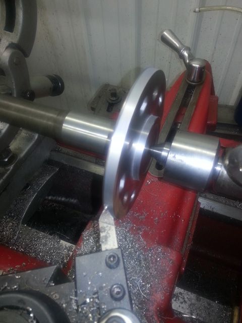
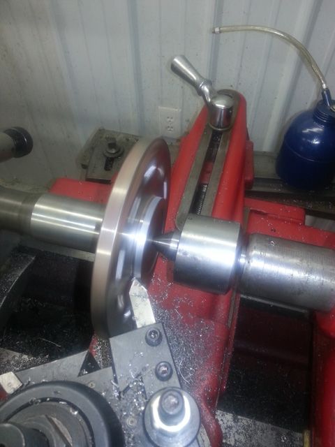
The axle and rotor bolt pattern was correct at 5 on 4 1/2", but I went ahead a drilled both for 5 on 4 3/4". I have been shopping for wheels and found some that I liked that were only available in the GM pattern. I don't know yet what I'm going to run, so it made sense to go ahead and do the work at this time.
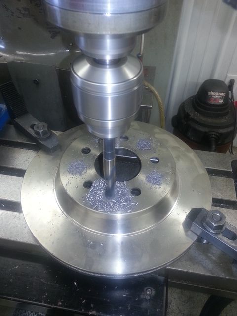
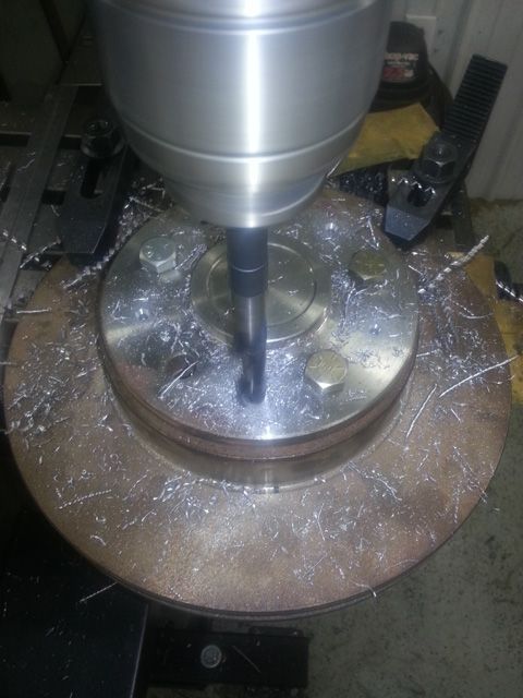
I used an old brake rotor as a holding jig so that I could hang the axles off of the mill table for drilling. Worked pretty good.
-
10-29-2016 09:15 AM #114
Once I had the axles back in and the rotors on (the first of many times during this project), I used the air fitting I made to mock the calipers in place. Luckily the brake line threads on the rear parts are the same as the fronts.
On the Mustang, the calipers mount behind the axle, but that wasn't going to work on this car. The emergency brake lever return spring was going to hit the coilover. I swapped to the front with the calipers, but the air bag was pretty close the return spring, too.
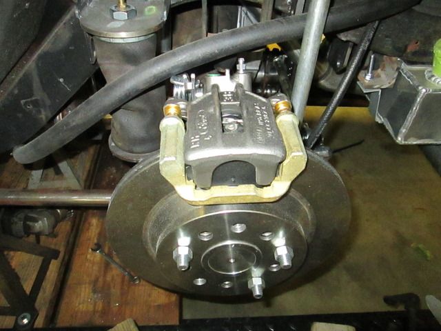
I tried them on top of the axle at the 12 o'clock position. They had plenty of clearance here, but had another problem. The inlet and the bleeder were both going to be on top and close together. This would most likely have caused bleeding problems.
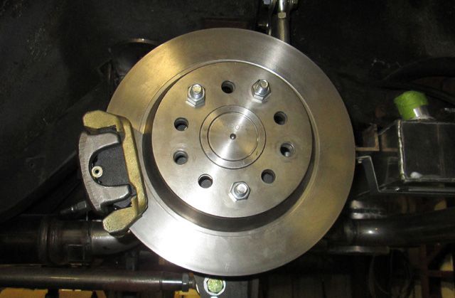
I wound up mounting them forward of the axle in about the 8 o'clock position. This put the inlet more or less on the bottom and the bleeder on top. That should eliminate any problems with trapped air. I also swapped sides with the calipers from their original positions. The driver's side caliper is now on the passenger side.
-
10-29-2016 09:23 AM #115
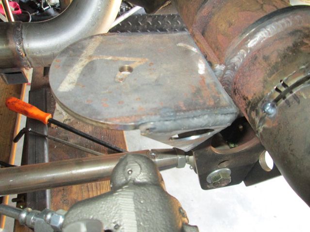
I have seen some brake swaps that mount the brackets on the back of the axle mounting flange. I'm sure this works OK, but Ford went to the trouble of machining the flange face square and leaving a small locating boss near the bearing. I decided to incorporate this boss into my brackets. The screwdriver is pointing to the boss in the pic.
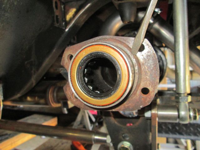
I made the brackets square while I was doing the initial work and then shaped them up after all the critical hole locations were found. Working with a square (squarish) form is just easier on the milling machine. According to my ratty old kitchen scales, the trimming relieved just shy of a pound from each bracket.
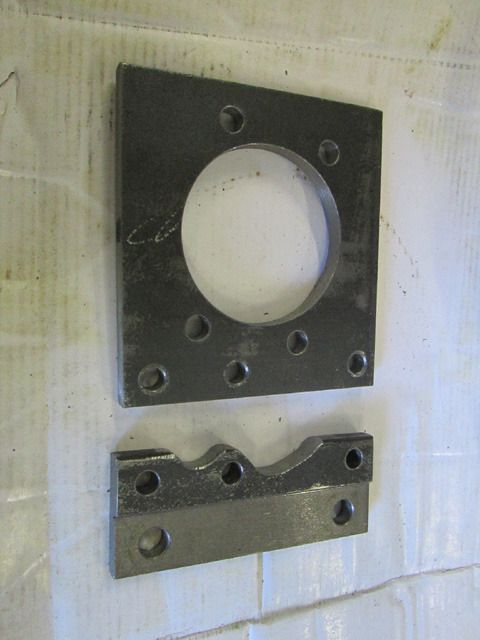
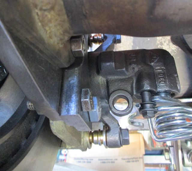
One area to look at if anyone decides to do something similar is clearance on the inside of the caliper area. Since these calipers are not fixed like an opposed piston caliper, they have to slide as the pads wear. I my case the caliper will get closer to the bag mount as the outside pad wears. It looks like I will have plenty of clearance here.
I was concerned that the E-brake cable would interfere with the axle tube. The Explorer tubes are larger than a regular Mustang axle. As it turns out, there is plenty of room.
When Ford installed these brakes on the Mustang, they used an additional brace called an "anti-moan" brace. It is essentially a triangulating bracket that clamps around the axle tube and attaches to the caliper mounting bolts. The rear brakes will sometimes make a groaning noise without this piece. I'll add my version of that brace when the rearend comes out next time and I have better access
-
10-29-2016 09:28 AM #116
I believe that I have accomplished what I set out to do. I now have oversize vented rotor brakes front and rear that should be suitable for limited track use if I want to. Considering that both brake sets came off of high performance cars that weight 1000 to 1500 lbs more that mine, they should stop this light car with ease. Performance grade pads are available and while the components weren't exactly dirt cheap, I don't have a ton of money in them. They may not be ultra-trick fixed position multi-piston calipers, but they will get the job done, I'm sure.
I'm pretty sure the rear brakes are lighter than the Explorer brakes by a pound or two. Even if they're the same weight, the vented rotors should give more consistent braking on the track. I read of at least one track that won't even let solid rear rotors through tech inspection. I doubt the front brakes are lighter than any of my other original choices (due to their size), but I'm sure the extra braking I picked up with the 13" brakes is going to be worth the weight. When I get a chance, I will weigh all the other combos and see how I came out.
There is a road course in New Orleans that does amateur instruction classes and open track days. I would love to do something like that (although I'm sure I'll be the slowest one on the track). That's one reason I'm going to the extra effort. That may never happen, but I can dream.
-
10-29-2016 10:42 AM #117
Wow, well done!
It's lookin' great. Congrats
-
12-04-2016 11:27 AM #118
Time for another series of updates.
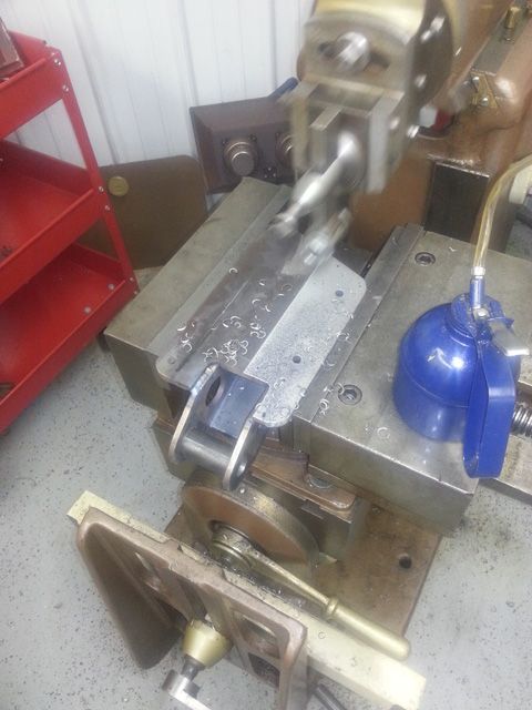
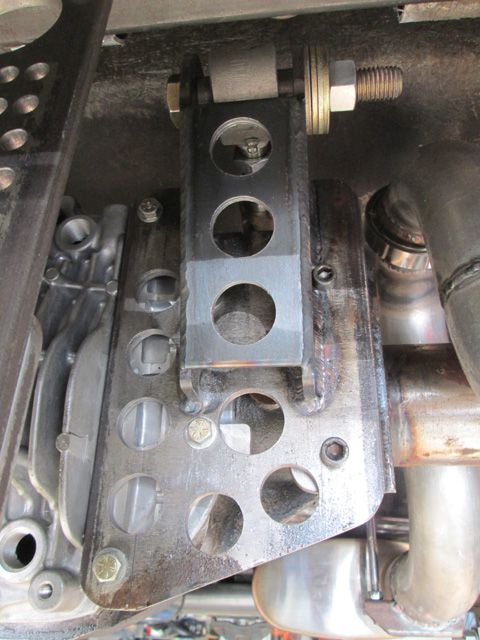
Another thing I took care of while I was working on the rear brakes was finishing the upper 3-link bracket. I had left it tacked together and oversize when I wound up the rear suspension and said I would finish it later. When I had the axles out for the brake fab, I decided that was as good a time as any to finish the bracket.
In spite of my best efforts at eliminating warping when I welded it, I still got a little. It wasn't going to sit flat, so I had to dress it off about 1/32". As promised earlier, I punched it full of "hot rod" holes, too. My old scales say that I shaved off 2 pounds even though I added a reinforcing plate between the ears.
Here's a before pic. Very roughly shaped, but it proved the concept.
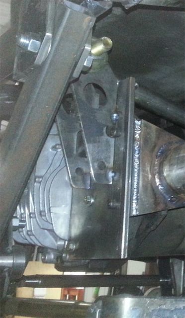
Here it is taking a ride in the shaper after welding.
And here's a finished shot.
-
12-04-2016 11:36 AM #119
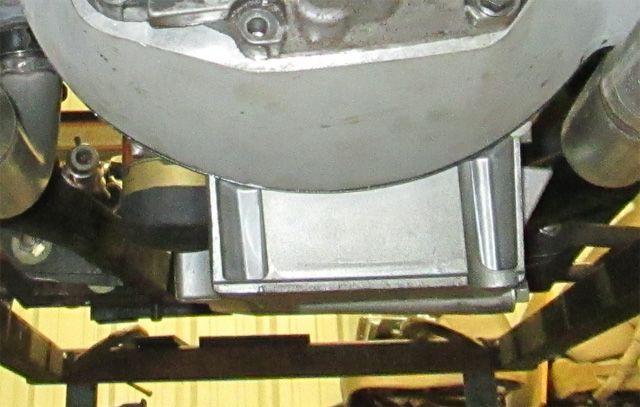
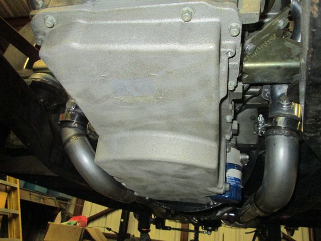
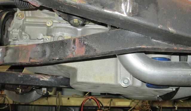
I also decided to swap out the oil pan. I'm going to start on anti-roll (sway) bars soon and plan on mounting them behind the axle. The pan might have interfered, but that wasn't the main reason for the swap. The truck pan that was mounted on the engine when I got it hung down way too far. It would have only had a couple of inches of ground clearance. The LS aluminum pans may be pretty stout, but they're not that stout. I chose an LS2 Corvette pan. I could have used the F-body (Camaro) pan as well, but the Corvette pan has a more baffeling. The bellhousing actually hangs down farther than the pan now.
Here's the pan before the swap. This wasn't going to work.
The new pan is much shallower.
-
12-04-2016 02:02 PM #120
Yep, you differently needed the extra ground clearance and the new sump pan looks just as cool anyway. I'm enjoying following along on this build with your engineering skills to make things and then to dress them to look cool as well as functional.I maybe a little crazy but it stops me going insane.
Isaiah 48: 17,18.
Mark.


 1584Likes

 LinkBack URL
 About LinkBacks
 Reply With Quote
 I can only imagine on both counts.


I check in everyday and some are better than others. I don't think Brent has anything to do with the forum anymore, but I'm not sure. Hopefully as time moves on the forum will get better.
Where is everybody?