


 1584Likes
Thread: Project Sebring GT Spyder


Results 61 to 75 of 838
 LinkBack URL
 About LinkBacks
-
02-14-2016 07:06 PM #61
 CHR Member

- Join Date
- Feb 2007
- Location
- Vidalia
- Car Year, Make, Model: 1946 Ford Coupe, 1962 Austin Healey 3000
- Posts
- 1,508
I've got a lot more construction pics. I'll try to get some more stuff up tomorrow night.
-
Advertising

- Google Adsense
- REGISTERED USERS DO NOT SEE THIS AD
-
02-15-2016 08:45 AM #62
CHR Member
- Join Date
- Mar 2009
- Location
- miami,coconut grove
- Car Year, Make, Model: 28rodster 292Y-block and HenryJ Olds V8
- Posts
- 262
Vary nice wook
-
02-15-2016 10:26 AM #63
CHR Member
- Join Date
- Sep 2007
- Location
- New Bedford
- Car Year, Make, Model: 34 Ford 3W Coupe Replica
- Posts
- 14,754
WOW! That's NICE!
-
02-15-2016 05:57 PM #64
CHR Member
- Join Date
- Feb 2007
- Location
- Vidalia
- Car Year, Make, Model: 1946 Ford Coupe, 1962 Austin Healey 3000
- Posts
- 1,508
Thanks guys. I put a lot of time and cussin' into it!
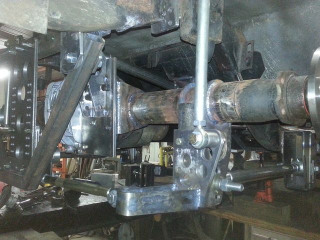
Both upper link mounts caused me a lot of trouble, but that's not uncommon. I studied the Factory Five Cobra/34 roadsters because they were the only cars that I could find that are similar to mine using a 3-link. I know someone that has a FF 34, so it was easy to get a good look at one.
FF hangs their upper axle link mount way out on the axle tube. Offsetting the upper link to the right helps to load that tire more under acceleration. Without any real design data to go on, I out started pretty much copying FF's mount on the rearend. I was well into that build when I found some fairly reliable info that recommended starting at 8-12% of track width. My car is has a narrower track than a FF car and putting it where they did would have put it well over 12% offset. Now it may still have worked fine, but I didn't want create a problem that couldn't be fixed without major surgery.
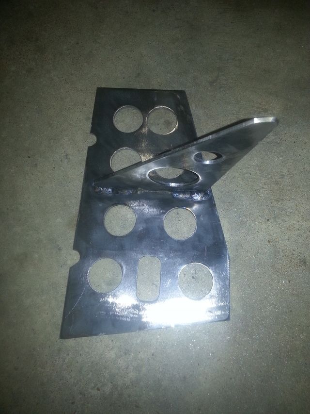
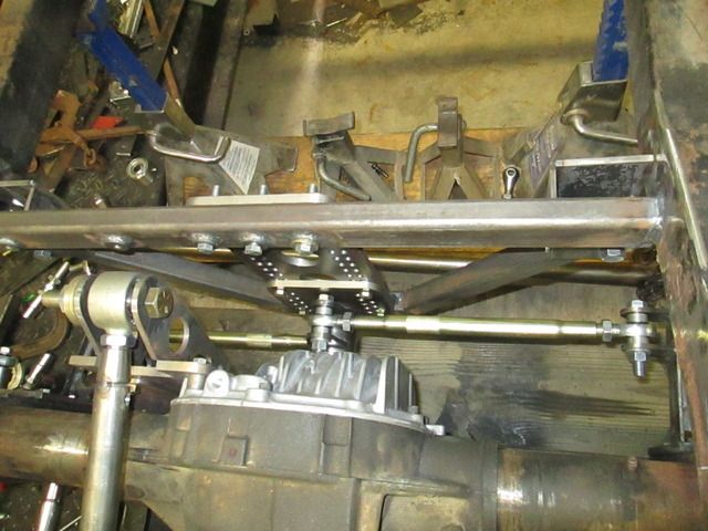
I scrapped all that I had built and started over. Because the 8.8 rear has a cast center section, I couldn't reliably weld the top link to the housing. I came up with a bolt-on link bracket.
I machined a section of the rear cover flat and made some steel spacers to go under the plate. It also bolts to a bracket welded to the axle tube. It's solid, but heavy(too heavy). When it comes off next time, it will go a serious diet. I need to do a lot of trimming and you can expect it to look pretty "swiss-cheesy" when I'm done with it.
-
02-15-2016 06:13 PM #65
CHR Member
- Join Date
- Feb 2007
- Location
- Vidalia
- Car Year, Make, Model: 1946 Ford Coupe, 1962 Austin Healey 3000
- Posts
- 1,508
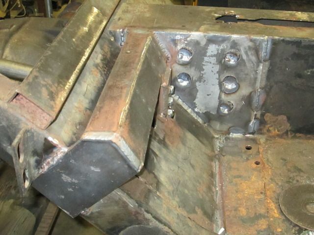
The upper frame mount had problems of it's own. The only solid thing to weld it to was the trans tunnel. The tunnel is a deep section box and is a pretty stout structure in the direction it'll be loaded, but it's thin.
I built a complicated mini-crossmember that tied into the tunnel with a large plate and stretched over to the frame rail. The cross piece had to be angle cut to match the back of the passenger compartment. There was just enough room to squeeze it in.
-
02-15-2016 06:34 PM #66
CHR Member
- Join Date
- Feb 2007
- Location
- Vidalia
- Car Year, Make, Model: 1946 Ford Coupe, 1962 Austin Healey 3000
- Posts
- 1,508
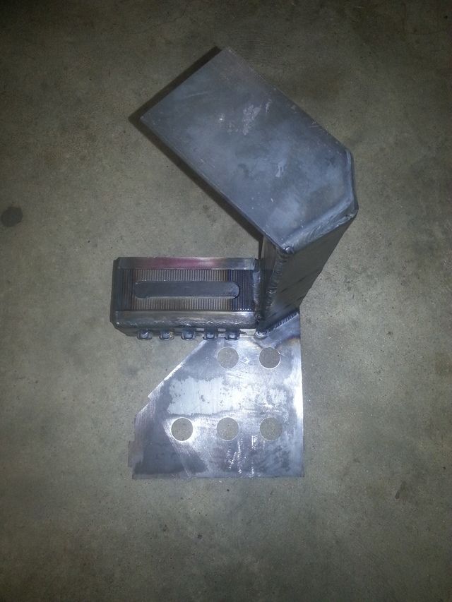
I couldn't just let the link adjustment "box" just hang down with no other support. I built a gusset that ties into the bottom of the link box and the floor. The gusset falls right on the same plane and level as the floor, so any stress is fed into a large area. I'm confident that this mount will handle a lot of horsepower.
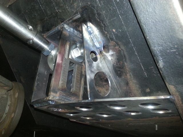
I also add a row of nuts to the back of the link box so that I could bolt on some boxing plates after I get it adjusted. These should reinforce the slot and keep it from spreading under load.
I have enough adjustment to get close to 100% anti-squat with no roll steer, but I'll never use that much. The info I've found says that for a car that goes around corners, about 40% is all you can use. Any more and the car starts to lose rear traction if you decelerate entering a corner. Of course, that's for a race car right on the limit of traction, a street car may be able to use a little more. It's available it I want to experiment.
-
02-15-2016 07:02 PM #67
CHR Member
- Join Date
- Feb 2007
- Location
- Vidalia
- Car Year, Make, Model: 1946 Ford Coupe, 1962 Austin Healey 3000
- Posts
- 1,508
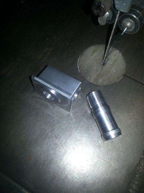
Here's a couple of videos. The first is the shaper working on the blanks for the sides of the link boxes. This will have a step in it for the adjustment serrations.
This one is the serrations being cut. It was a looooooong process. My wife says that machine work is like watching paint dry!
-
02-15-2016 07:06 PM #68
CHR Member
- Join Date
- Feb 2007
- Location
- Vidalia
- Car Year, Make, Model: 1946 Ford Coupe, 1962 Austin Healey 3000
- Posts
- 1,508
I'll put some stuff about the Watts link up tomorrow.
-
02-16-2016 05:11 PM #69
CHR Member
- Join Date
- Sep 2007
- Location
- New Bedford
- Car Year, Make, Model: 34 Ford 3W Coupe Replica
- Posts
- 14,754
Your wife is right! At least a shaper has a motion you can follow. The horizontal looks like the travel was painfully slow.
-
02-16-2016 05:28 PM #70
CHR Member
- Join Date
- Feb 2007
- Location
- Vidalia
- Car Year, Make, Model: 1946 Ford Coupe, 1962 Austin Healey 3000
- Posts
- 1,508
It's not as bad as it looks. That's a horizontal attachment on my Bridgeport CNC. It doesn't have full CNC capacity, but I can write simple short programs. I really didn't have to sit and stare at it the whole time. The program did all the boring repetitive stuff. I was running it with a fairly slow feed rate to protect the cutter. I only had one with that contour.
-
02-16-2016 06:31 PM #71
CHR Member
- Join Date
- Feb 2007
- Location
- Vidalia
- Car Year, Make, Model: 1946 Ford Coupe, 1962 Austin Healey 3000
- Posts
- 1,508
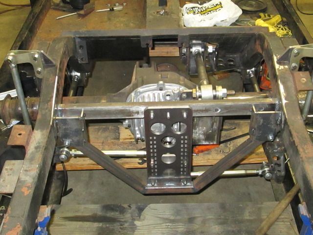
I could have mounted the watts link rocker on the rearend, but chose to mount it to the frame. If you put it on the rearend, the roll center stays the same height from the ground, but the relationship with the center of gravity changes as the suspension moves. Mounting it on the frame keeps the distance to the center of gravity constant.
The argument for frame mounting says that since the tires are loaded by weight transfer acting from the center of gravity through the roll center, frame mounting gives more consistent tire loading. This made sense to me, but lots of folks mount it on the rearend with apparently good results.
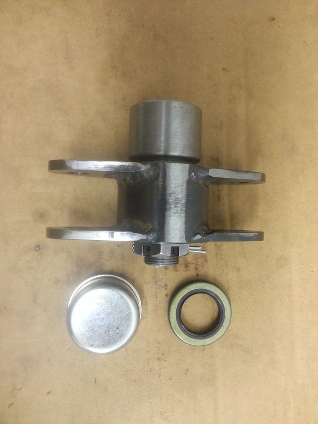
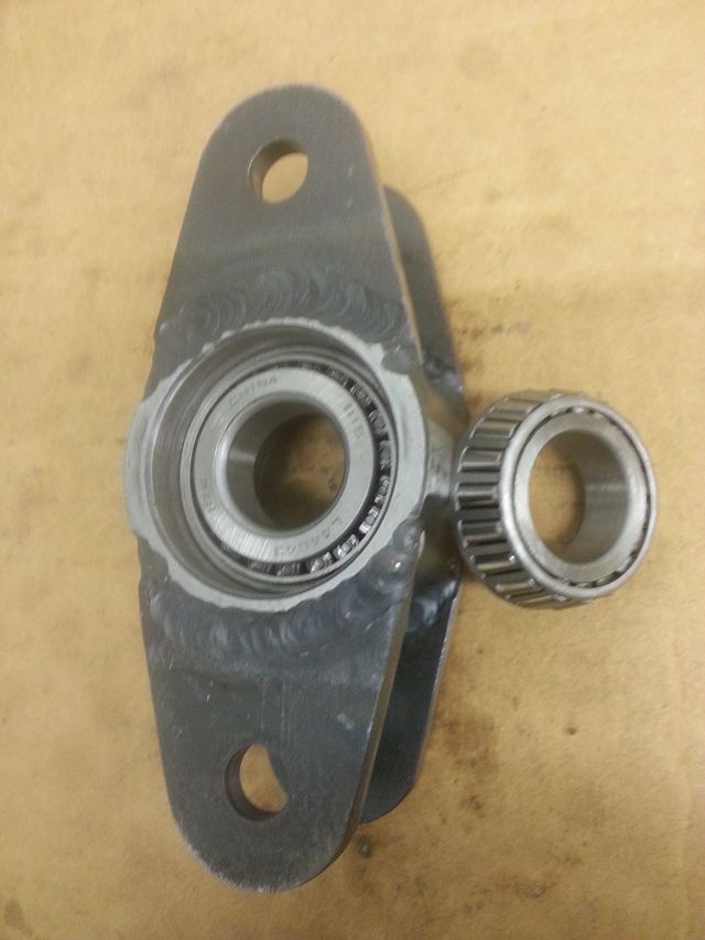
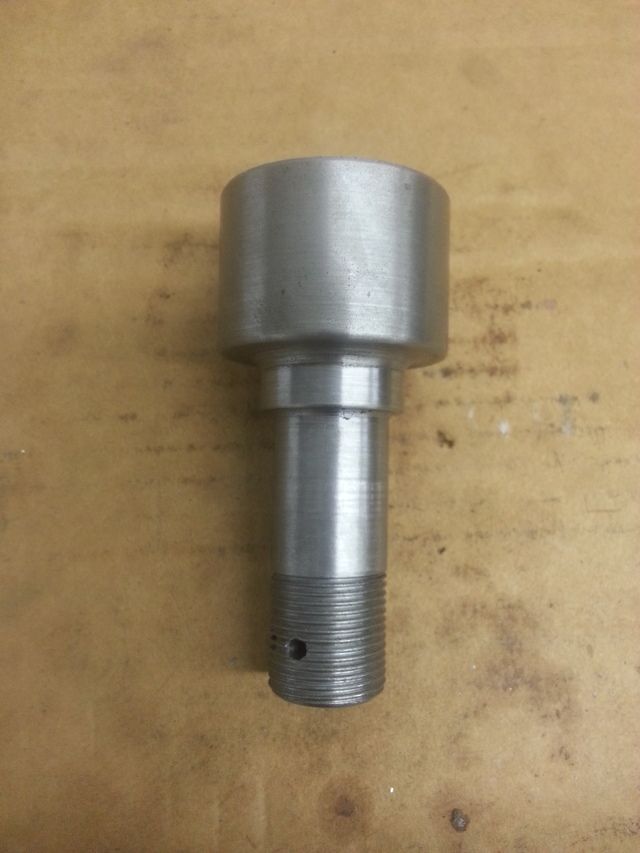
I built the rocker to take tapered bearings like a wheel. Actually, the bearings are 1" trailer bearings. I used a kit that serviced one trailer wheel. I had to make a short spindle. If I had mounted it to the rearend, I would have carved the rocker out of aluminum to save weight. Since I hung it off the frame, I used steel.
Last edited by Hotrod46; 02-16-2016 at 07:55 PM.
-
02-16-2016 06:53 PM #72
CHR Member
- Join Date
- Feb 2007
- Location
- Vidalia
- Car Year, Make, Model: 1946 Ford Coupe, 1962 Austin Healey 3000
- Posts
- 1,508
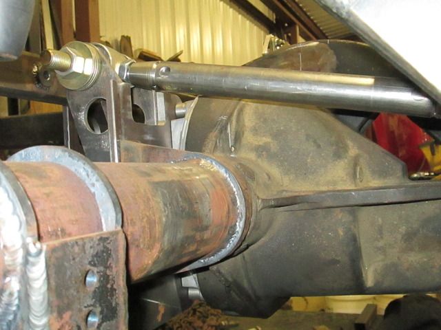
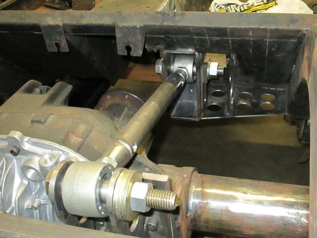
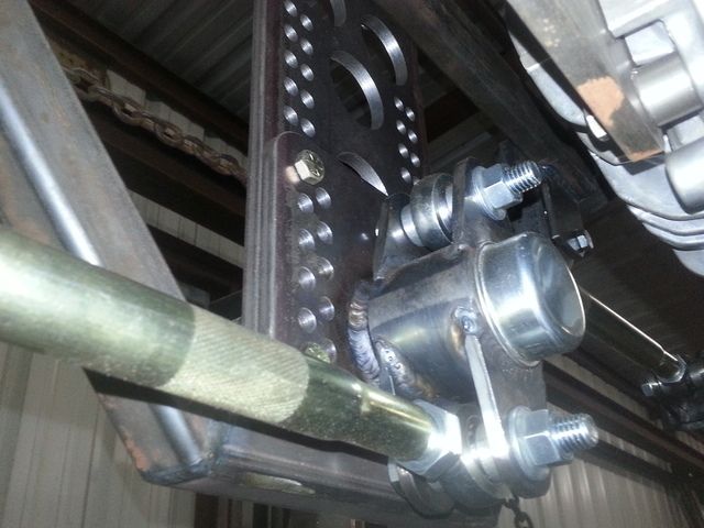
The frame that holds the watts link had to bolt in. If it didn't, working on the rearend would have meant pulling the whole rearend out.
I had originally intended to use poly bushings in the link ends, but there is too much movement fore and aft. The bushings were going to have to flex in a direction that they didn't have much give. I swapped over to heim joints. If I was building it over again, I would use tie rod ends. That's what Chrysler did on the PT Cruiser. It has a watts link on the rear axle.
The center rocker can be raised and lowered in 3/8" jumps to move the roll center.
I still have some rough edges to clean up and most of it is just tacked together. I have a lot of welding left on the whole car. I'm waiting until I strip the chassis down so I can position it for better access.
-
02-17-2016 12:26 PM #73
CHR Member
- Join Date
- Sep 2007
- Location
- New Bedford
- Car Year, Make, Model: 34 Ford 3W Coupe Replica
- Posts
- 14,754
I must admit. I've never seen a watts link NOT mounted to the rear axle!
The picture(s) made me think about it's motion / travel... ;-)
-
02-18-2016 07:02 PM #74
CHR Member
- Join Date
- Feb 2007
- Location
- Vidalia
- Car Year, Make, Model: 1946 Ford Coupe, 1962 Austin Healey 3000
- Posts
- 1,508
I decided I needed to reinstall the rear body section to check some clearances and do some future build planning. To do this, I needed to repair the broken and bent rear body mounts. There is no way that these mounts can be accessed without removing the rear body section. That's another reason I decided to tear the car down in the first place.
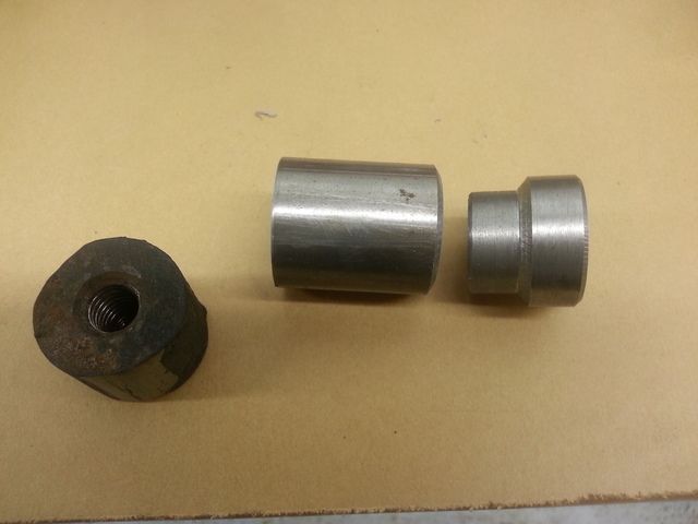
These mounts were originally simple pieces of angle iron with a threaded bushing welded on. A 1 1/4" aluminum sleeve extends this bushing through the rear of the body. This body area is reinforced and serves to locate the body on the chassis. The aluminum sleeves are also used to mount the rear bumper brackets. The threaded bushing on the driver side was broken off. The weld appeared to be poor, with little penetration. You can see how much the mounts were bent. I could have used heat to straighten them, but decided to cut them off and build new ones.
I built my new mounts differently than the originals. I salvaged the threaded bushings and welded them to short sections of DOM tubing. These were welded to a long flat bar that spaced them out for the body openings. The bar was slotted and bolted on with carriage bolts. The slotted bar gives me some lateral adjustment of the body position and the nuts can be accessed with the body on. I had noticed that the rear fenders were not centered over the chassis and this adjustable mount will allow me correct this.
When I attempted to set the body section in place I got a surprise. The body wouldn't fit! The lower roll pan that wraps under the chassis was hitting the rear leaf spring mounts. I was 100% sure that I had the new "straight" mounts in the right place. After thinking it over, I came to the conclusion that the rear mounts had not gotten bent in an accident as I had thought. I don't think the body fit correctly from the beginning and whoever built this car purposely bent them down to "adjust" the body to clear the spring mounts. That explains why the bends were fairly consistent on both sides. The rear bumper was bent, so the car did take a little hit at some point, but probably not enough to bend the mounts. Chances are, the weld on the driver side bushing was damaged during the original bending and the bumper hit finished breaking it off. As I said earlier, it's automotive archaeology. My conclusions might be completely wrong.
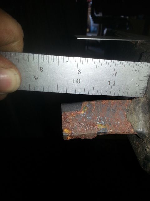
I didn't really need the spring mount, so I trimmed it for clearance. I left most of it because it might come in handy for hanging the exhaust. If I don't use it, I'll remove it completely when I tear the car down for finish welding.
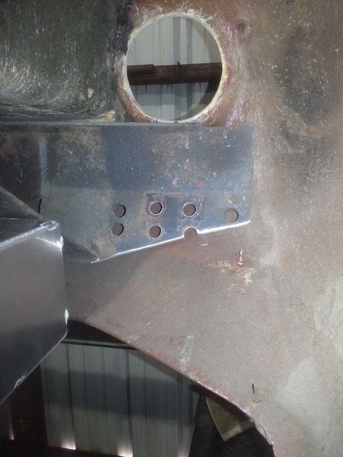
This is after trimming. You can see the light colored scratches where the mounts contacted the body.
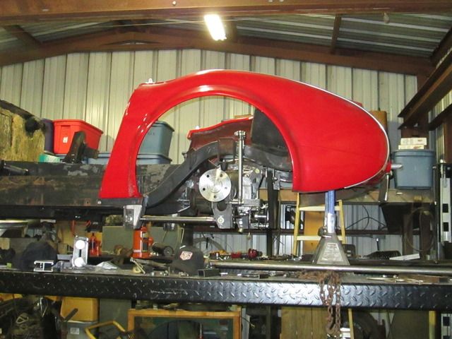
After the trimming, the body section slipped on just fine. At least it's looking a little more like a car now. I did manage to get the axle centered in the wheel wells this time around. The original axle was off center by about an inch.
-
04-23-2016 09:26 AM #75
CHR Member
- Join Date
- Feb 2007
- Location
- Vidalia
- Car Year, Make, Model: 1946 Ford Coupe, 1962 Austin Healey 3000
- Posts
- 1,508
OK. It's been a few months and a lot has happened, including a little work on the car!
I decided to take a break from suspension and get a few other things done. I still have a long list and decided to concentrate on the fuel and exhaust systems. No particular reason for choosing those other than they needed to be done.
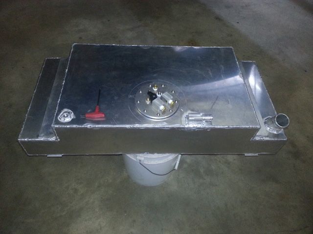
I wanted to run a decent sized fuel tank. I could only get about 10-11 usable gallons in the original Chevette tank. It was supposed to hold more, but venting problems made it pretty much impossible to fill completely. It may have also been a gauge sending unit error and I wasn't going to take a chance on walking to press my luck by running it down below "E".
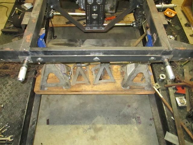
I wanted to keep the tank bottom as high as I could so that exhaust wouldn't be more difficult to run than it was already going to be. Snaking around the watts link was going to be challenge enough. Four inches seemed like a reasonable number, so that wound up being the under frame depth. To get a fair volume, I had to build the tank up between the frame rails as well as having a section below.
The dimensions are 36x16x4 on the lower section and 26x16x3 on the upper part. This works out to 15.3 gallons. Not as much as I had hoped, but still better than I had. As you can see from the pictures, I added a small round sump to the bottom. I'm running an in-tank EFI pump and this gives a small quantity of fuel (.4 gallons) that won't slosh away from the pump.
Pump starvation is a real problem for EFI cars that are asked to go fast around curves. The really serious setups use a separate 1 gallon or so surge tank to feed the EFI pump that is fed by a separate low pressure pump. My setup is a simpler compromise that should work OK for street use. The tank has a couple of large baffles to keep sloshing down and some additional vanes on the bottom that funnel fuel toward the sump. The hole in the tank bottom is smaller than the sump forming a lip that should keep gas from crawling out under G's. This lip was formed down into a rough funnel shape, too. The watts link frame should offer some protection for the sump.
To keep from running the filler hose through the already small trunk, I put the fill pipe in the lower section. This required a large vent in the upper part. The vent hose is 3/4" and I am hoping that this will vent quick enough to allow reasonable fill-up time. It will eventually connect to the upper part of the fill hose near the gas cap and will only come into play when the cap is open. The normal running vent is a 5/16" line that will connect to a roll over valve mounted high under the rear fender.
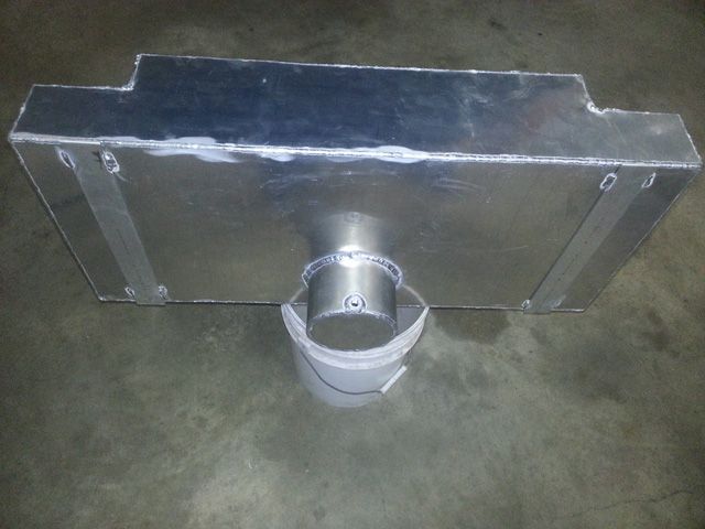
This is the large vent that I made for the top section.
 Reply With Quote


Posting Permissions
- You may not post new threads
- You may not post replies
- You may not post attachments
- You may not edit your posts

i've enjoyed the years here . made a lot of friends. most who have left. i see no reason to continue with this so hope to see you somewhere else. i dont think this site will ever be back. it's lived...
Dead!