


Thread: Front coil-overs
Results 1 to 15 of 21
 LinkBack URL
 About LinkBacks
Threaded View
-
02-02-2008 02:08 PM #1
 CHR Member

- Join Date
- Sep 2006
- Location
- Deer Lodge
- Car Year, Make, Model: '27 T Coupe
- Posts
- 793
Front coil-overs
I have built a new frame and suspension, IFS & IRS with a Nissan 300ZX posi rear end, with 4 wheel disc brakes for my wifes '27 T Tudor Sedan, It only needs the shocks, old chassis worked, but it's just not what I wanted! It will also have the Vortec 4.3 out of our '93 S-10 Blazer (after we move).
I have a question about the new front & rear coil-overs, when I order new ones, the front span I have is 10" at ride height, do I get 12" so that I would have 2" down (tire goes down) travel on the shock? or is that already figured in when they say the length?
They will sit at 20 degs, unless I set them at a 12" span then the angle changes to about 17.5 degs. I can change the mount on the frame and use a longer shock if I want to.
Thanks! PatHemiTCoupe
Anyone can cut one up, but! only some can put it back together looking cool!
Steel is real, anyone can get a glass one.
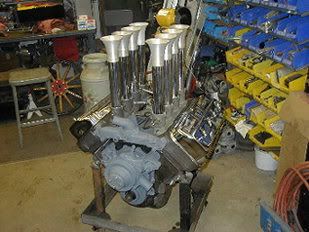
Pro Street Full Fendered '27 Ford T Coupe -392 Hemi with Electornic Hilborn injection
1927 Ford T Tudor Sedan -CPI Vortec 4.3
'90 S-15 GMC pick up

 Reply With Quote
Posting Permissions
- You may not post new threads
- You may not post replies
- You may not post attachments
- You may not edit your posts

This site is up more often lately, but very little traffic.
Dead!