


Thread: Front coil-overs


Results 1 to 15 of 21
 LinkBack URL
 About LinkBacks
-
02-02-2008 02:08 PM #1
 CHR Member

- Join Date
- Sep 2006
- Location
- Deer Lodge
- Car Year, Make, Model: '27 T Coupe
- Posts
- 793
Front coil-overs
I have built a new frame and suspension, IFS & IRS with a Nissan 300ZX posi rear end, with 4 wheel disc brakes for my wifes '27 T Tudor Sedan, It only needs the shocks, old chassis worked, but it's just not what I wanted! It will also have the Vortec 4.3 out of our '93 S-10 Blazer (after we move).
I have a question about the new front & rear coil-overs, when I order new ones, the front span I have is 10" at ride height, do I get 12" so that I would have 2" down (tire goes down) travel on the shock? or is that already figured in when they say the length?
They will sit at 20 degs, unless I set them at a 12" span then the angle changes to about 17.5 degs. I can change the mount on the frame and use a longer shock if I want to.
Thanks! PatHemiTCoupe
Anyone can cut one up, but! only some can put it back together looking cool!
Steel is real, anyone can get a glass one.
Pro Street Full Fendered '27 Ford T Coupe -392 Hemi with Electornic Hilborn injection
1927 Ford T Tudor Sedan -CPI Vortec 4.3
'90 S-15 GMC pick up
-
Advertising

- Google Adsense
- REGISTERED USERS DO NOT SEE THIS AD
-
02-03-2008 12:04 AM #2
CHR Member/Contributor
- Join Date
- Nov 2007
- Location
- Calgary
- Posts
- 496
I'll admit I don't have the background like most guys here but I did read that 60 percent is for bump travel and 40 percent for rebound. I noticed in the Speedway catalogue they are sold as approximate mounting length. Mine are advertised for 11.5" but they are actually around 15.5".
Hope that helps,
Sean.
-
02-03-2008 08:29 AM #3
CHR Member
- Join Date
- Feb 2004
- Location
- Barrie-Ontario-Canada
- Car Year, Make, Model: 1931 Roadster Pickup
- Posts
- 2,016
As far as I know, the advertised shock "length" is the pin to pin measurement at mid travel---50% of total available travel. The shock "travel" is the actual difference between fully extended and fully retracted. A parts house will have both of those numbers for any shock.Old guy hot rodder
-
02-03-2008 08:51 AM #4
CHR Member/Contributor
- Join Date
- Jul 2003
- Location
- Madison
- Car Year, Make, Model: '67 Ranchero, '57 Chevy, '82 Camaro,
- Posts
- 21,160
Coilovers are spec'd at their actual extended and retracted length.... I would suggest checking the specs on the one's you're interested in and make a solid strut of some sort to simulate the coilover at ride height, 50% to 60% of it's length depending on which school of thought you endorse, and use this mockup height to determine the exact angle and length for you coilovers.....Yesterday is history, tomorrow is a mystery, Live for Today!
Carroll Shelby
Learning must be difficult for those who already know it all!!!!
-
02-04-2008 03:11 PM #5
CHR Member
- Join Date
- Sep 2006
- Location
- Deer Lodge
- Car Year, Make, Model: '27 T Coupe
- Posts
- 793
Thanks for the reply's!
I have everything finished except, to weld the bottom shock mounts to the front lower A arms. At ride height I can fit anything from a 8" to a 13" long shock, but the more they tip over the stronger the springs, rate shocks I'll need to get, to the rate on the shocks I need.
I was wrong on what I wrote that 10" shocks sit at 17.5 degs, they are at 27degs. I don't think I want 12" shocks because they will lean to much.
I machined all the parts and 5 left & 5 right hand jigs to hold the A arm parts, so that I could weld them correctly the first time!
I also built a frame jig, everything is right on & square!!!
On my Coupe, I was going to buy a Chassis Works rear frame clip for my Coupe, (I had gotten a frame from some one had, that they change theirs out for a different one, I see why now) but now I'm going to build a complete whole new frame myself, I already have it drawn up on MasterCad, I'm building everything myself, F&R 4 link bars and mounts, Watt's link, the rear-end is already 9" shorten to 41.5" with plates.
After doing everything the right way on the Sedan frame/chassis , I know that I can redo my Coupe frame & chassis myself.
Pat
Anyone can cut one up, but! only some can put it back together looking cool!
Steel is real, anyone can get a glass one.
Pro Street Full Fendered '27 Ford T Coupe -392 Hemi with Electornic Hilborn injection
1927 Ford T Tudor Sedan -CPI Vortec 4.3
'90 S-15 GMC pick up
-
03-07-2008 10:55 AM #6
CHR Member/Contributor
- Join Date
- Jul 2007
- Location
- Upland
- Posts
- 398
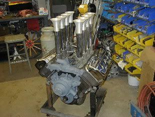
I want that motor- stuffed between the rails of a Deuce!
-
03-07-2008 11:38 AM #7
CHR Member
- Join Date
- May 2003
- Location
- Zephyrhills, Florida, USA
- Car Year, Make, Model: '32 Henway
- Posts
- 12,423
First off, there is nothing to keep you from fabricating more than one mounting point on the frame. Visualize the mounting brackets on a 4-link. The bracket could include holes for mounting the shock at 5, 10, 15 and 20 degrees for instance. You'd want the adjustable bracket on the frame instead of the control arm.
Determine how much wheel travel you will have in bump and droop and install your bump stops accordingly. Let's say you have 4" in bump and 4" in droop from the "at rest" position. Now, measure from the hat where the wheel bolts up to the pivot point on the lower control arm. Let's say that is 16". Now let's say you find a shock with a travel of 4". You now know that the shock will have to be installed at a distance of 8" from the pivot point of the lower control arm in order to use the shock's full 4" of travel at vertical (no lean). The more you lean the shock, the less travel it will have, so you have a built-in safety factor to keep from tearing the shock apart or bottoming it out when you install it at an angle.
When I talked to Aldan about shock mounting, they suggested 55% in bump and 45% in droop. I had shocks with a 4" range, so multiplying 4 times .55 told me to install them at 2.2" extended from their mid-travel point, leaving 1.8" for droop. I don't think it makes a lot of difference if you use 50% or 55% or whatever, just as long as you have your bump stops set correctly to keep from destroying the shocks.
-
03-07-2008 07:10 PM #8
CHR Member/Contributor
- Join Date
- Jul 2003
- Location
- Madison
- Car Year, Make, Model: '67 Ranchero, '57 Chevy, '82 Camaro,
- Posts
- 21,160
Another chart you may want to look at deals with selecting spring rates based on the mounting angle of the coilovers.....It's on the Speedway Motors site. I've always used it and found it to be quite accurate!!!!Yesterday is history, tomorrow is a mystery, Live for Today!
Carroll Shelby
Learning must be difficult for those who already know it all!!!!
-
03-08-2008 08:04 AM #9
CHR Member
- Join Date
- Sep 2006
- Location
- Deer Lodge
- Car Year, Make, Model: '27 T Coupe
- Posts
- 793
This is on the front of a "T", I don't have a lot of room for a top shock mount,(I already have a small bumb in the fenders for it) and the lower mount I can move to where I want it, but it will be welded in place once. I don't have bump stops in the front yet.
The front shocks sit at 27 degrees at ride height & 10.5 between shock mount, it can be made longer, but the shock will lay down more, which decrease the shock movement, which then I have to increase shock spring weight also.
Should I have some camber angle change when the wheels are raised (as hitting a bump in the road) mine now are set for .035 change (tire lean) in a 4" stroke. If I raise the lower "A" frame inner mount up 1.875, I get 1" lean on the tire, in a 4" stroke. The more I can raise it the better.
Pat
Anyone can cut one up, but! only some can put it back together looking cool!
Steel is real, anyone can get a glass one.
Pro Street Full Fendered '27 Ford T Coupe -392 Hemi with Electornic Hilborn injection
1927 Ford T Tudor Sedan -CPI Vortec 4.3
'90 S-15 GMC pick up
-
03-08-2008 11:11 AM #10
CHR Member
- Join Date
- May 2003
- Location
- Zephyrhills, Florida, USA
- Car Year, Make, Model: '32 Henway
- Posts
- 12,423
I got my instruction by reading Carroll Smith's books and as I remember it all came together for me after Tune To Win. I had read many other author's offerings, but they stopped short of really explaining how to design the system. Smith explained how to play with paper dolls to scale (I didn't have the advantage of software as you do). I played with it, re-positioning everything until I had minimum scrub, 3 degrees of camber gain in 4 1/2 inches of bump and zero bump steer through 9 inches of travel. The camber gain was achieved with the angle of the upper control arm while the lower arm was flat. The lower the frame mount end of the upper control arm is, relative to the ball joint end, the more camber gain you will achieve.
By the way, I have seen ball joint extenders for sale that allow more camber gain by angling the upper arm.Last edited by techinspector1; 03-08-2008 at 11:22 AM.
-
03-08-2008 09:15 PM #11
CHR Member/Contributor
- Join Date
- Jul 2003
- Location
- Madison
- Car Year, Make, Model: '67 Ranchero, '57 Chevy, '82 Camaro,
- Posts
- 21,160
I would doubt that your real suspension movement in normal driving conditons will be 4", probably more like 2" to 3". 3 to 4 degrees of camber gain in anything less then all out road racing competition would be negligible as long as the bumpsteer remains a zero throughout the full range of travel...... We played with camber gain and roll centers a lot in the circle burner cars, but as long as the settings are reasonable they don't seem to have much of an effect on street driveablity. Bumpsteer on the other hand, can turn a pleasure trip into a nightmare! With the camber gain as you describe it, what caster angle will you be adjusting into the front end? It's been my experience that caster and bumpsteer settings are far more important on the street then anything else in the front end geometry....Yesterday is history, tomorrow is a mystery, Live for Today!
Carroll Shelby
Learning must be difficult for those who already know it all!!!!
-
03-08-2008 10:57 PM #12
CHR Member
- Join Date
- May 2003
- Location
- Zephyrhills, Florida, USA
- Car Year, Make, Model: '32 Henway
- Posts
- 12,423
Dave's right about the travel. It's just that I overbuild everything. For instance, I used 1.000" X 0.188" chromoly tubing for the upper and lower control arms. That front end would have been equally at home under a military 6x6 driven offroad. I think it was Pat Ganahl who wrote that he saw over 100 failed suspensions on rod runs every year and so I set out to make mine bulletproof.
In retrospect, 1.000" x 0.125" for the lowers and 0.750" x 0.083" for the uppers would have been more aesthetically pleasing and a God's plenty from a strength standpoint.Last edited by techinspector1; 03-08-2008 at 11:00 PM.
-
03-09-2008 10:08 AM #13
CHR Member/Contributor
- Join Date
- Jul 2003
- Location
- Madison
- Car Year, Make, Model: '67 Ranchero, '57 Chevy, '82 Camaro,
- Posts
- 21,160
I found that chart on spring rate adjustments for shock angle..... Thought I would post it, I know the question has been asked a few times.Yesterday is history, tomorrow is a mystery, Live for Today!
Carroll Shelby
Learning must be difficult for those who already know it all!!!!
-
03-09-2008 02:38 PM #14
CHR Member
- Join Date
- Sep 2006
- Location
- Deer Lodge
- Car Year, Make, Model: '27 T Coupe
- Posts
- 793
Thanks Guys,
I was checking my graphs I make to check my radius swings of the arms, and camber gain. I have it set right now at a 3" up movement it tilts 3/8" top to bottom of a 26" tire @ 2.4 degrees good enough. I have 6 degrees anti-dive in the upper A arms mounts. the R&P I'm using lines up with the intersection of the upper and lower A frame pivot point, and level with the spindel arms, which means no bumb steer. But! I have to change the one I have, because Dave said, "You can't find the 16" mount one, use the 15.5" one.
I do need to find out (I'm going to get one later, after I move, but need the number now) what the width of the 15.5 rack is, at the inner pivot of the tie rod.
I already have the R&P mounts made, But not welded on yet.
I drew all this up about 5 years ago, then welded the frame up, using a frame jig I built to hold everything right on! not close. I welded every weld 4 times in steps, 1 to hold, and 3 to fill, and then I ground every weld to a smooth 5/8's radius! no filler  You could say I had some time to kill at one time every thru hole has a tube in it . then I had to pick up all my toys and pack them to remodel the house, and sell it, that was three years ago and everthing is still packed. So I thought I would start to work on the suspension parts again.
All parts are made on jigs I made for each one. even made a jig to mount my A frame/anti-dive mounts. Shock mount are also made, but not welded on yet.
My front IRS is made from a Mustang II front end I had laying around, the only parts I used are the power R&P, spindels and brake parts. (new rotors and calipers) , mopar screw in ball joints, 1.00X.125 seamless tubing A frames & rear rods, I made all my own greaseable poly & steel suspension bushings everywhere, The top A frames are adjustable, the bottoms are not F&R. rear toe-in, caster, camber is adjustable, front & rear width hub to hub is 57", welded up the hubs & rotors and redrilled them all the same bolt pattern
The car also has a Nissan 300ZX posi IRS it it, so I had to make all the jigs for those A frames & rods also.
I have everything made, I just need to make the final adjustments to the front shocks, and make sure I have the front pivot points set right. The rear is all done, I need to weld the front shock mounts on and it will stand on it's tires. and then I can switch out the frames on the wifes '27 T Tudor Sedan
Dave, Thanks, I have the same charts, and more, but none tell me if I buy a 12" shock is it 12" extended all the way out, or at it's mid travel. or do I get a 12" and take 50-60 % off it's stroke and thats what I use? What is the actual stroke of a 12" shock?
I can tell you that 1 degree per inch is appox .017, but I cant figrue my shock lenght!
I'll ask you guys more yet! I just think I know it all! ")
Pat
I don't like it hanging on the wall, I want to set it on it's wheels
Anyone can cut one up, but! only some can put it back together looking cool!
Steel is real, anyone can get a glass one.
Pro Street Full Fendered '27 Ford T Coupe -392 Hemi with Electornic Hilborn injection
1927 Ford T Tudor Sedan -CPI Vortec 4.3
'90 S-15 GMC pick up
-
03-09-2008 02:50 PM #15
CHR Member/Contributor
- Join Date
- Jul 2003
- Location
- Madison
- Car Year, Make, Model: '67 Ranchero, '57 Chevy, '82 Camaro,
- Posts
- 21,160
Actually the length of stroke on a coilover depends on the manufacturer... I use AFCO or one of the other dirt track suppliers for my coilovers these days. The street rod people seem to think we should all be happy with about 3" of stroke, they obviously drive on nicer roads then I do...!!!!! I much prefer to have 5" to 7" of travel. This usually requires a bit of re-engineering on the attach points, but the extra travel is really worth it when it comes to tuning in the ride and handling!!!!! On the rear of the 'maro I'll probably use a pair of "Pro" large body aluminum shocks... They are threaded for coilovers and can be bought with really good travel, up to 9" of it!!!! Trying to work a deal on a set of Bilstein's for the Ranchero.... They are both kind of spendy, but ya get what ya pay for!!!!!!
Also have a friend of mine who does motocross forks and shocks for a living... He's getting ready to buy a new shock dyno and I'm first in line to get his old one...... Then I can do the insides of the coilovers with the valving and gas load that I want!!!!!Yesterday is history, tomorrow is a mystery, Live for Today!
Carroll Shelby
Learning must be difficult for those who already know it all!!!!
 Reply With Quote

Posting Permissions
- You may not post new threads
- You may not post replies
- You may not post attachments
- You may not edit your posts

This site is up more often lately, but very little traffic.
Dead!