


 3390Likes
Thread: 55 Wagon Progress
Results 1,591 to 1,605 of 1865
 LinkBack URL
 About LinkBacks
Threaded View
-
01-10-2013 07:27 PM #1
 CHR Member

- Join Date
- Jun 2008
- Location
- Leonardtown
- Car Year, Make, Model: Walking
- Posts
- 1,228
55 Wagon Progress
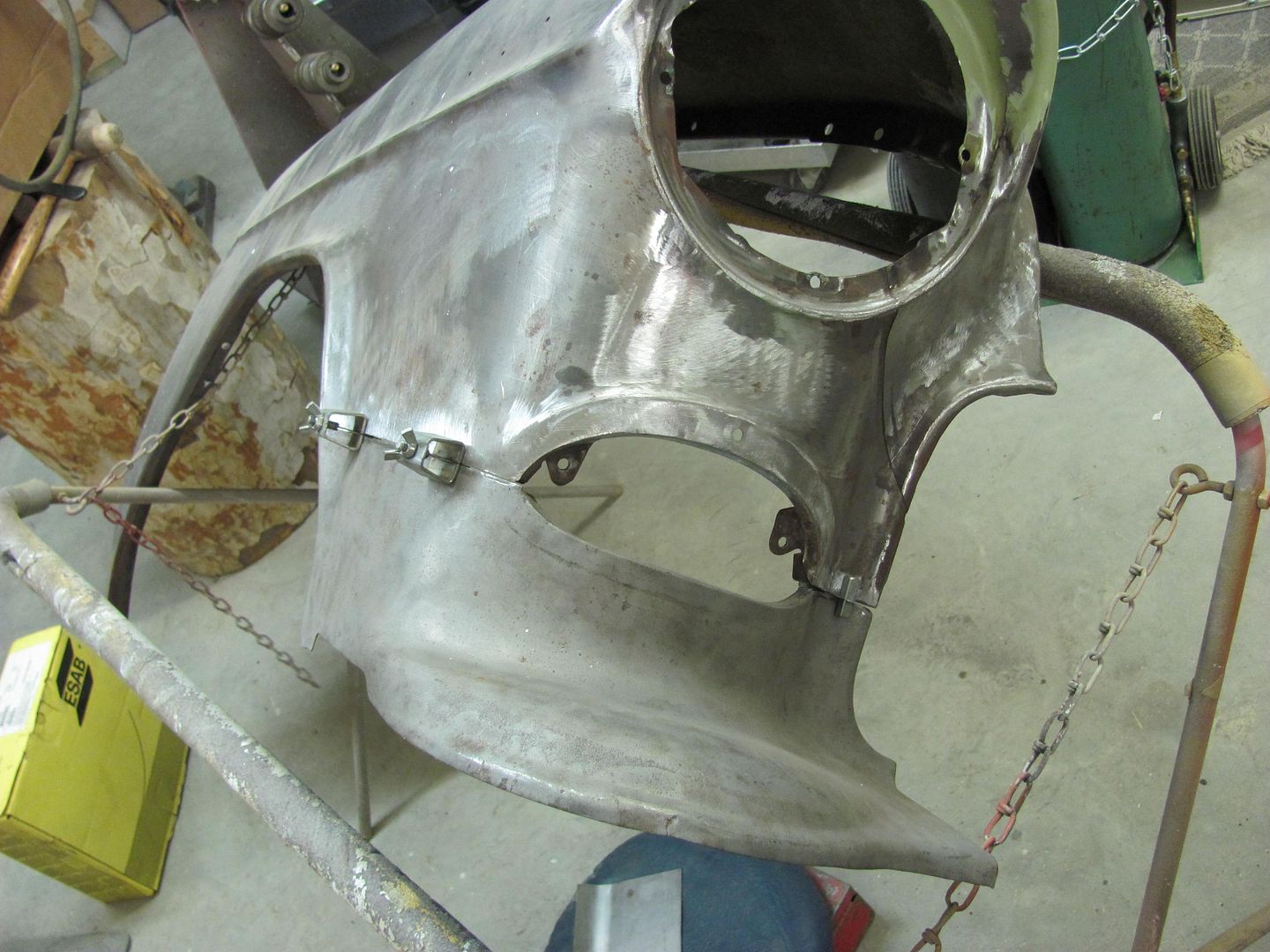
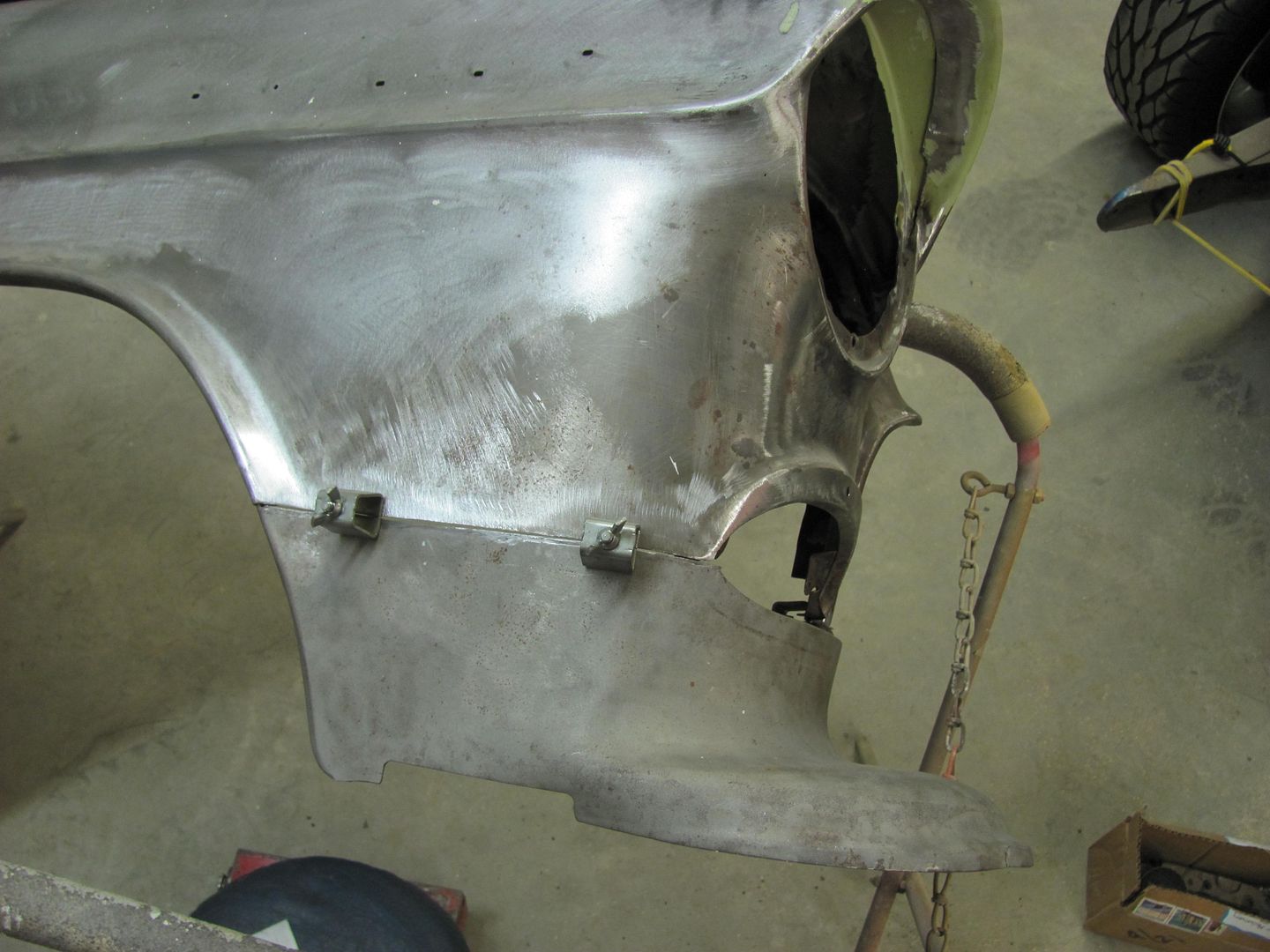
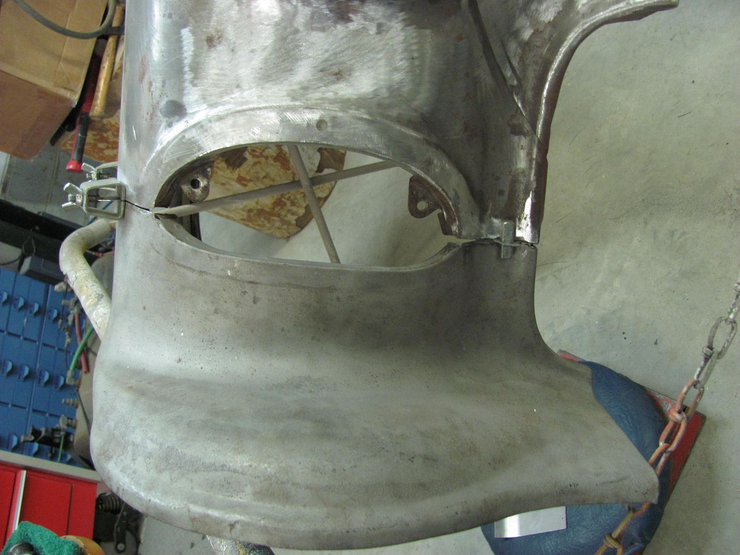
This is a customer car, the owner and I discussed shaving the fender seams quite a while back, and she asked about it again last week, so I guess we're on the hook..
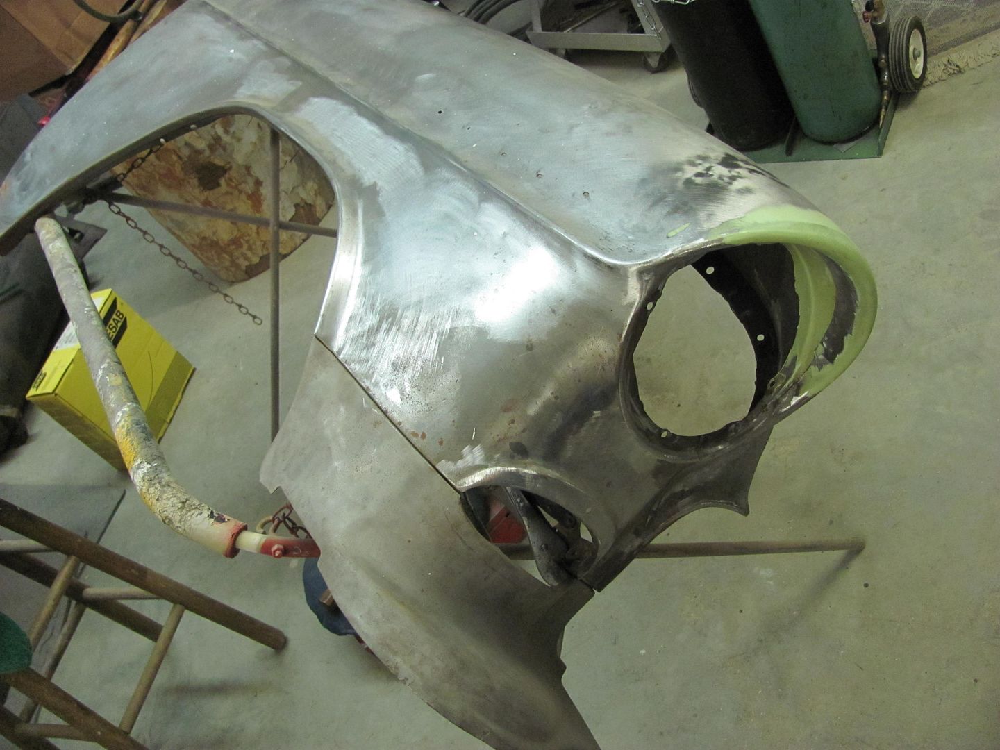
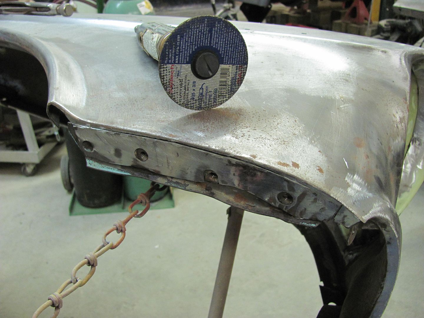
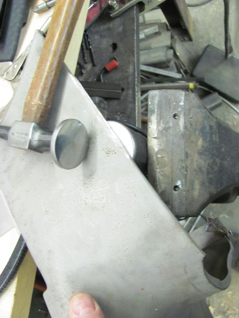
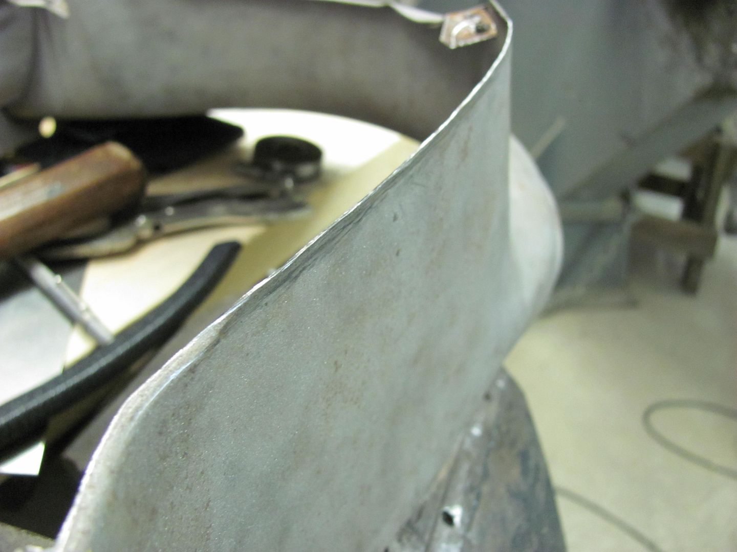
The bolting plates are cut out of the way, and the folded flange is trimmed, leaving a bit of extra to allow for fine tuning the weld joint.
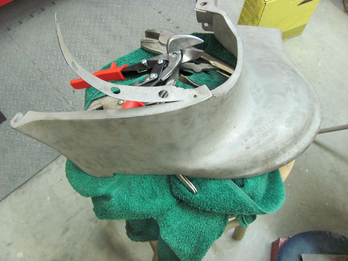
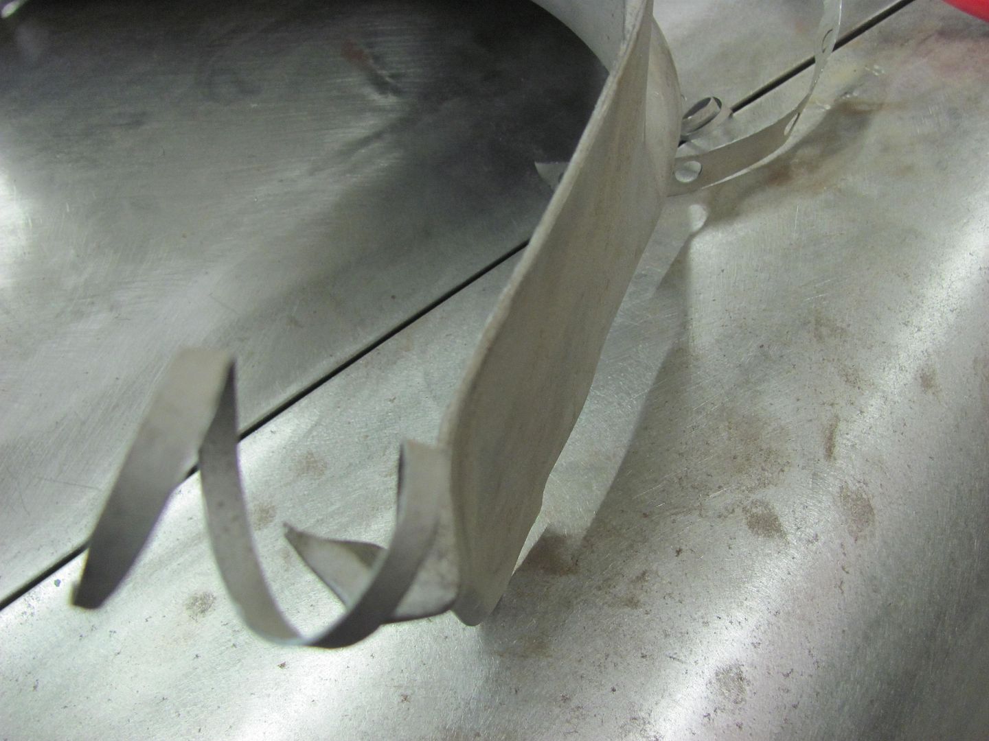
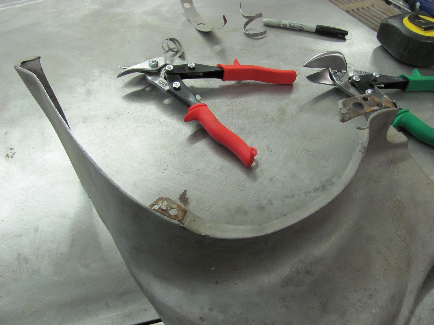
Bottom of the fender is cut loose from the bolting plate using the cutoff wheel. Then sanding the face of the fender leaves a contrast at the bend of the flange for a good guide for trimming with snips....
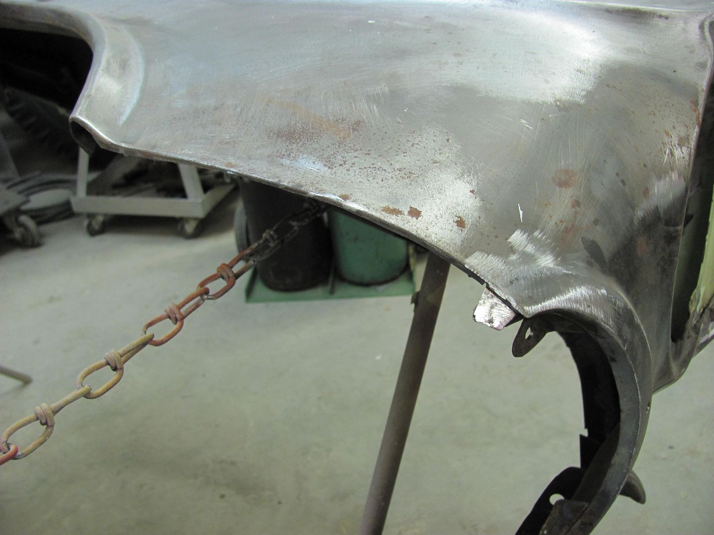
Planishing out the fold to fill the gap....
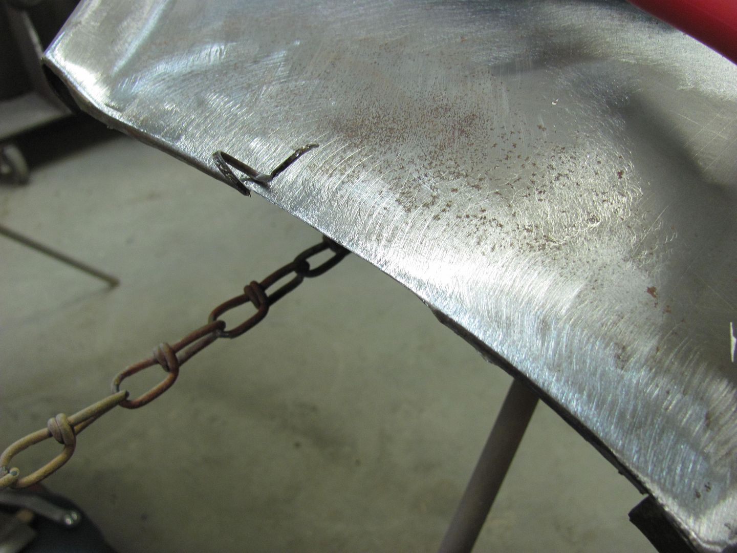
Clamps used to test fit. Still needs some fine tuning for zero gaps, but we'll finish that another day..
Robert

 Reply With Quote
Posting Permissions
- You may not post new threads
- You may not post replies
- You may not post attachments
- You may not edit your posts

Either return this forum to what was or get the HELL OUT!
Dead!