


 4Likes

Results 256 to 270 of 334
 LinkBack URL
 About LinkBacks
-
12-08-2008 01:29 AM #256
 CHR Member

- Join Date
- Feb 2007
- Location
- Vidalia
- Car Year, Make, Model: 1946 Ford Coupe, 1962 Austin Healey 3000
- Posts
- 1,499
JR
I already have a proportioning valve plumbed in. I put it in when I still had the discs on the front just in case I needed it.
BTW Your car is looking great!
Mike
-
Advertising

- Google Adsense
- REGISTERED USERS DO NOT SEE THIS AD
-
12-28-2008 06:04 PM #257
CHR Member
- Join Date
- Feb 2007
- Location
- Vidalia
- Car Year, Make, Model: 1946 Ford Coupe, 1962 Austin Healey 3000
- Posts
- 1,499
 It's going back together!!
Now that Christmas is over, I thought I would take time to post an update. I hope everyone had a good holiday.
First things first, though. I have to make a correction to an earlier post.
Turns out that my math was off in my post about the wheel cylinders. The 1 and 15/16 combo Im using actually gives me a 12% difference instead of the 19% figure that I posted.
The 1 1/8 and 1 combo would actually be 21% difference.
I had refigured everything for my post and dont even know where I got those numbers. Must have left my brain somewhere else that day!
Sorry if I caused anyone to be confused.
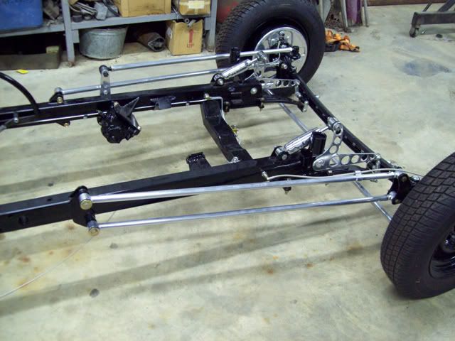
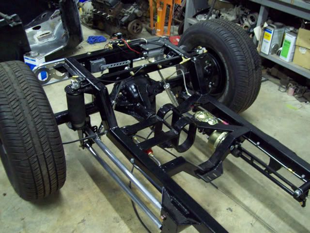
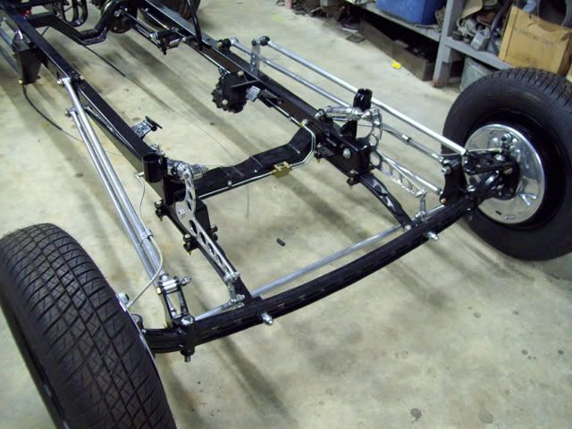
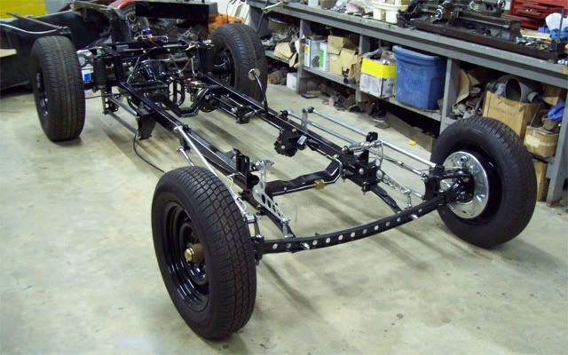
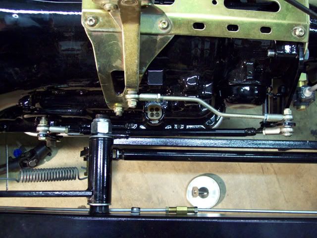
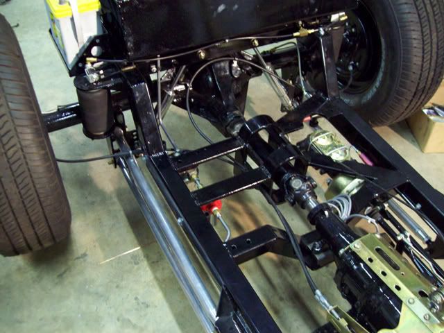
The frame front and rear suspensions have been assembled and squared. I still need to set the pinion angle and the caster on the front end. Im waiting until the engine is in for this step. I can go over all the bolts then and make sure they are tightened and locked.
The air compressor, valves and air bags are all mounted and plumbed. The valves are small 1/8 stainless steel units, but they're big enough for what I'll be using them for. I mounted a valve directly to each bag using solid pipe fittings to keep the two sides of the car separate. Each bag will be a separate "spring", so there shouldn't be any air transfer from bag to bag when the car leans. Should also help keep any small leaks at the tubing connections from bleeding the bags down overnight since they're essentially sealed. It has been aired up for about 2 weeks now and doesnt appear to have leaked down.
When I was testing this setup earlier in the build, it only took about 30-40 lbs. of air to hold the car at ride height with one person on board. I would be surprised if it took more than 50-60 when it was fully loaded. Each bag has an 800 lb rating at 100 PSI. There is one valve with a restrictor mounted on an aluminum manifold to bleed off air, so only 3 valves are needed for the whole system. There is no air tank; the air compressor will push air directly into the bags. During earlier testing, the compressor took only a few seconds fill the bags if they were empty. There is a safety switch on the distribution manifold that will kill the compressor if the system gets to 105 PSI.
Im using a GM control switch to keep the ride height where I want it. These were used on high end GM cars in the 70s through the 90s. They are not much bigger than a pack of cigarettes and attach to the frame. An arm and linkage attaches to the rearend. The length of the link determines the ride height. Not as sophisticated as the programmable controllers on the market today, but theyre usually cheap and as close as your local junk yard. Add a couple of automotive relays and youre good to go.
Hard to see in the pics, but I rounded the ends of the leaf springs to make them look a little better. I also added a third leaf to the front spring packs. I didnt feel real confident about using just two leafs. These are heavier ¼ thick leafs.
I spent a lot of time chasing threads and fitting parts where they were powder coated. Note to self: Dont build this stuff so tight if youre going to powder coat it! The ceramic coating is aluminum based, so I used liberal amounts of anti-seize compound. I didnt want to risk galling the threads.
The brakes are bled, but not without some problems. I had a new wheel cylinder leaking!! No, it wasnt one of the modified cylinders. It was one of the new ones I bought for the front. I pulled it apart and found that it was full of crap that looked like kitty litter. Nothing was damaged, but the crud had gotten under the cup lips and wasnt allowing it to seal. After cleaning it up everything was fine, but I use a pressure bleeder and it sure made a heck of a mess before I saw it was leaking. I hate to think that Im going to have to start pulling NEW parts down and check them before I use them. More of that good Chinese crap!
All of the hard fuel lines, the fuel pump and filter are installed. I still have to make up the braided flex lines for the fuel system.
The engine and trans is going in tomorrow.

-
01-06-2009 08:01 PM #258
CHR Member
- Join Date
- Feb 2007
- Location
- Vidalia
- Car Year, Make, Model: 1946 Ford Coupe, 1962 Austin Healey 3000
- Posts
- 1,499
I got a lot accomplished on my days off over the holidays.
The shifter is on and the linkage is finally worked out. I wound up fabbing the long link out of ½ steel tubing, since the all-thread Lokar provides wasnt stiff enough when bent to clear the brake pedal.
The engine and trans are together and in the frame.
The alternator is back together and installed on the engine. Same with the fan, pulleys and belt.

I reprimed the oil pump (just to be sure), reinstalled the distributor and retimed the engine to 10 degrees BTDC.
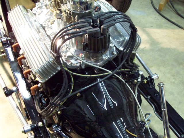
The body had to be dropped back on (temporarily) to check the routing of the spark plug wires around the steering shaft. I had to make up a couple of mounts for the Made For You looms Im using, but the wires tuck in nice under the headers AND clear the steering.
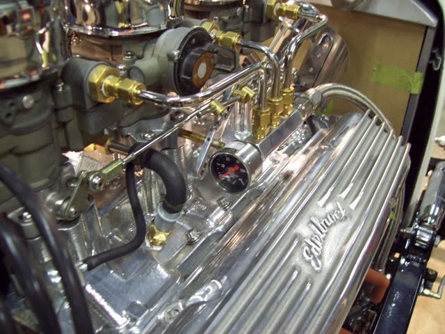
The fuel pump and filter unit went back on with all of the plumbing. I made up the braided hose that runs from the regulator to the fuel manifold on the engine. Im using a regulator because these 2Gs dont need more than 4-4½ PSI. I also drilled the rear of the fuel manifold and installed a fuel pressure gauge.
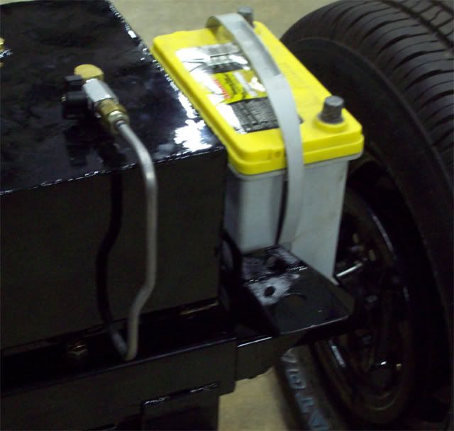
After running the hard line from the tank to the pump, I realized that I wouldnt be able to pull the tank with the body on. I had to add a coupling so that the upper bend could be removed.

The trans cooler lines are back on and the transmission throttle valve cable (Lokar) is installed. I got lucky because the trans cable stud on the throttle arm was pretty close to where it needs to be for a 700R4. If youve never used a 700 before, you need to know that the location of that stud is very important. It needs to follow a specific radius as the throttle is opened or you can burn your trans up. That info can be found here:
http://purplesagetradingpost.com/sum...o/700R4p1.html
The driveshaft is assembled, installed and the pinion angle is set. On the front I set the caster angle at 6 degrees.
The emergency brake cables are hooked up and partially adjusted. I left them a little loose for now because the handle needs to be straight up for the body to go on. When the body is bolted on, Ill give it the final adjustment.
I also moved the body to a location in the shop where I can get started on the sanding and body work. If the weather permits next week, I may start on some of that. I can always work on the frame while its cold, but the paint likes the weather a little warmer.
Because I tend to work slower than Christmas, I have hesitated to set a firm time goal for getting this thing on the road, but there are two shows in March that I would really like to take it to. I figure I can make it pretty easily, but Im going to have to paint when I can. Might not have any interior, though.
When my off time ran out, I was working on final fitment of the radiator, shell and plumbing.
Mike
-
01-06-2009 08:14 PM #259
CHR Member
- Join Date
- Jan 2006
- Location
- fort myers
- Car Year, Make, Model: '27 ford/'39 dodge/ '23 t
- Posts
- 11,033
Mike, I have been watching this car come together since the beginning and really really like the way it looks and the way you are doing it. Everything just looks so right, and now that you are getting all of the paint and shiny stuff on it looks spectacular. You are down to the short strokes now bud.
I agree with Jim, the proportioning valve should take up any mismatch. I have 12 inch 46 Ford brakes with Buick drums on the front and S10 9 or 10 inchers on the back, with a Mustang master cylinder. It balanced out fine, so I think you will be ok too. The lightweight of these cars helps a lot too.
I've looked at your latest pictures several times and find new stuff every time I do...........very interesting, cool car. Get er done.........you are near the finish line.
Don
-
01-06-2009 08:40 PM #260
CHR Member
- Join Date
- Feb 2007
- Location
- Vidalia
- Car Year, Make, Model: 1946 Ford Coupe, 1962 Austin Healey 3000
- Posts
- 1,499
Don
Thanks!
Yeah, it feels good to be getting close. The little details are taking a lot of time, but I think I'll make March OK.
Mike
-
01-07-2009 05:51 AM #261
CHR Member
- Join Date
- Oct 2007
- Location
- Petaluma
- Car Year, Make, Model: 48 Ford F1
- Posts
- 9,778
Ditto what Don said, it looks great. Love the gloss black details."  "No matter where you go, there you are!" Steve.
-
01-07-2009 07:22 AM #262
CHR Member
- Join Date
- Apr 2001
- Location
- Salado
- Car Year, Make, Model: 32, 40 Fords,
- Posts
- 10,856
I should be as slow as you...............") Very nice progress.
Very nice progress.
You might want to spend a few words on your discreet PCV mounting and the sourcing for the distributor cap that allows the neat wire routing.Your Uncle Bob, Senior Geezer Curmudgeon
It's much easier to promise someone a "free" ride on the wagon than to urge them to pull it.
Luck occurs when preparation and opportunity converge.
-
01-07-2009 07:35 PM #263
CHR Member
- Join Date
- Feb 2007
- Location
- Vidalia
- Car Year, Make, Model: 1946 Ford Coupe, 1962 Austin Healey 3000
- Posts
- 1,499
Thanks guys.
Bob
The distributor cap is just a stock Standard Parts unit from my local parts house. The trick is the way the distributor is installed and timed. Looking down from the top, #1 is at approximately 11 oclock with the rotor pointing more or less at cylinder #1. Set up like this you get cylinders 1, 5 and 7 on the left of the cap and 8, 4 and 6 on the right. Cylinders 2 and 3 of course have to cross over. I run these under and behind the distributor and line everything up with the Made for You looms. The looms go a long way to cleaning up the look. The 90 degree ends at the distributor gives the set up a look that reminds me of the old crab distributor caps.
The PVC set up uses a hidden baffle made from junk I had laying around. I used a ½ stainless high pressure pipe plug, which is just a solid rod threaded for ½ pipe. I drilled this all the way through and tapped it for ¼ internal pipe threads on the same end as the ½ external threads. The actual baffle is made from 1 square tubing with a couple of small pieces of flat stock welded in to form a labyrinth. I know it looks kind of crude, but I think it will get the job done. The manifold is drilled and tapped for ½ pipe threads from the bottom and the breather screws in with the threaded end just above the outside of the manifold.
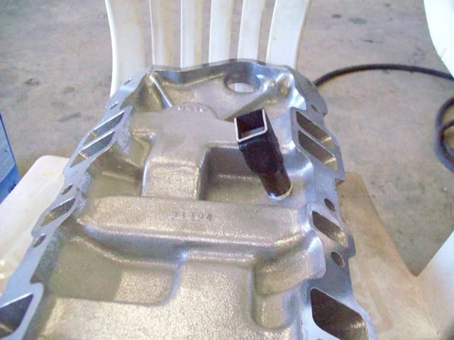
I originally intended to use a screw in PCV valve from a 65 327 Vette, but none of the parts places carried that valve. What they stocked for that application was an inline style valve that had a 3/8 hose connection on the carb end and a ½ hose connection on the manifold end. I used a ½ compression fitting with ¼ pipe threads to convert the inline valve to screw in. If you cut the expanded portion of the 1/2 hose fitting off of the valve, the stub that is left will fit in the compression fitting just fine.
The hose is just a PCV 90 degree molded piece from my local parts house. Sorry, I dont know what it fits, but Ive seen similar hoses on the Help isle at some chain parts places. The carb fitting is a compression fitting with a short piece of stainless tubing.

Mike
-
01-07-2009 08:12 PM #264
CHR Member
- Join Date
- May 2003
- Location
- Zephyrhills, Florida, USA
- Car Year, Make, Model: '32 Henway
- Posts
- 12,423
Mike, I just read the last page of this thread. I haven't kept up with it, but was reading your wheel cylinder data and math.
The difference between a 1" and a 15/16" cylinder is 6.25% (.9375/1=.9375)(1.000 less .9375=0.0625 or 6 1/4%) If you want to go the other way with it and divide, it's (1.000/.9375=1.06666 or 6 2/3%)
Either way you look at it, going larger to smaller or smaller to larger, if you're changing it by one sixteenth, it's 6% and change.
One your other example, the 1 1/8" and 1", the math is as follows: (1.000/1.125=0.8888) (0.8888 subtracted from the whole number 1.000= 0.1112, or just over 11%)
Dividing the other way, (1.125/1.000= 1.125 or 12 1/2%) Depending on which way you look at it, going from larger to smaller or smaller to larger, it's 11-12%.PLANET EARTH, INSANE ASYLUM FOR THE UNIVERSE.
-
01-08-2009 02:28 AM #265
CHR Member
- Join Date
- Jul 2003
- Location
- Titusville, FL
- Car Year, Make, Model: 31 Ford Coupe; 32 Ford 3-window
- Posts
- 1,783
Wow! What a cool idea for your PCV system. With everything else in place, it practically disappears. I would never have thought of that if you gave me the parts and a year to think about it. I'll definitely file that one to the "memory banks".
The whole thing is really looking good, Mike. What is the intended paint scheme for the body?
Jim
Racing! - Because football, basketball, baseball, and golf require only ONE BALL!
-
01-08-2009 05:41 AM #266
CHR Member
- Join Date
- Nov 2007
- Location
- Bonita Springs
- Car Year, Make, Model: 23 Ford T, 2004 ZO6 Vette, 99 Mustang
- Posts
- 542
Great looking car! Awesome attention to detail and I love all of you "trick" engineering. Looks fantastic! Don Jr.Don Jr.
"Once again I have thoroughly disgusted myself"
-
01-08-2009 07:40 AM #267
CHR Member
- Join Date
- Feb 2007
- Location
- Vidalia
- Car Year, Make, Model: 1946 Ford Coupe, 1962 Austin Healey 3000
- Posts
- 1,499
Thanks guys!
Tech - I was using piston area to figure the percentage. 15/16" = .69029 square inches and 1" = .7854 square inches .69029/.7854 = .8789 1-.8789 = .1211 or 12% of the area. I used area because that is what is actually doing the work. Good to know someone is interested enough to check up on me! I did spend a little TOO much time reading Hot Rod mags in math class. Miss Terry said that would catch up with me one day!
MikeLast edited by Hotrod46; 01-08-2009 at 07:43 AM.
-
01-08-2009 08:51 AM #268
CHR Member
- Join Date
- Feb 2007
- Location
- Vidalia
- Car Year, Make, Model: 1946 Ford Coupe, 1962 Austin Healey 3000
- Posts
- 1,499
JR
Sorry, I intended to answer your paint question in my earlier post, but CRS kicked in.
I'm going to keep the black on black theme going. Straight black PPG single stage. I've got a lot of sanding and priming to do!
There is a good pin striper about 2 hours from my house and I've been intending all along to get him to lay down some lines when it's all done. Probably some "Von Dutch" type stuff similar to what Don had put on his.
The interior color is still up in the air. Probably a darker red color like oxblood or deep maroon. I've even thought about black, but that might be too much black. I'd love to go with a "distressed" type of vinyl, but don't know if it's available in marine grade material.
MikeLast edited by Hotrod46; 01-08-2009 at 05:51 PM.
-
01-08-2009 11:18 AM #269
CHR Member
- Join Date
- May 2003
- Location
- Zephyrhills, Florida, USA
- Car Year, Make, Model: '32 Henway
- Posts
- 12,423
You're correct. I should resist writing this stuff in the wee hours of the morning. Originally Posted by Hotrod46


Last edited by techinspector1; 01-08-2009 at 11:21 AM.
PLANET EARTH, INSANE ASYLUM FOR THE UNIVERSE.
-
01-08-2009 05:15 PM #270
CHR Member
- Join Date
- Oct 2004
- Location
- Edgerton
- Car Year, Make, Model: 59 Corvette 283/270 69 C10 Stepside 355
- Posts
- 162
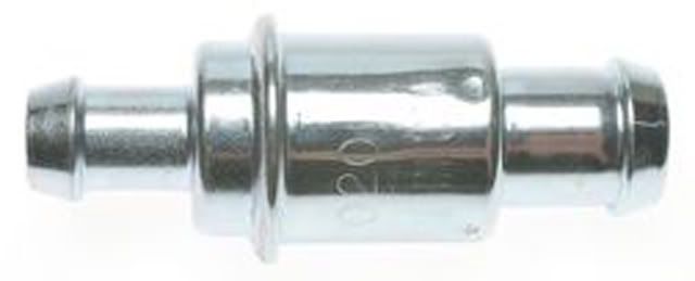
Is this what you were looking for? Originally Posted by Hotrod46
PCV Valve
 Reply With Quote

Posting Permissions
- You may not post new threads
- You may not post replies
- You may not post attachments
- You may not edit your posts

The main function of your little toe is to make sure all the furniture in the house is in the right place.
the Official CHR joke page duel