


 4Likes

Results 181 to 195 of 334
 LinkBack URL
 About LinkBacks
Hybrid View
-
12-06-2008 08:35 PM #1
 CHR Member

- Join Date
- Feb 2007
- Location
- Vidalia
- Car Year, Make, Model: 1946 Ford Coupe, 1962 Austin Healey 3000
- Posts
- 1,508
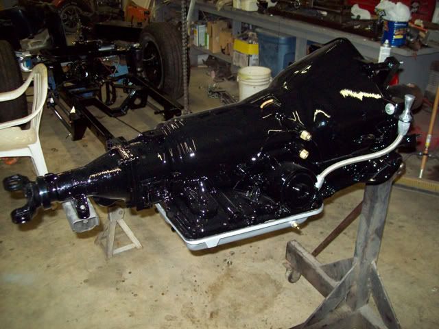
The trans was one of the things I had left to paint.
I also changed out the lockup pressure switch on the valve body. It is now wired to lock in 4th gear or I will be able to select lockup in 2nd, 3rd and 4th.
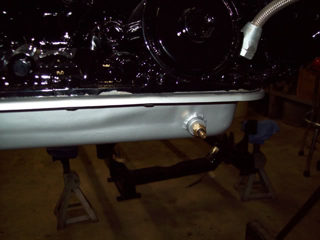
I had a chrome pan for it, but it turned out to be a piece of Chinese junk! The bolt holes were off just enough to prevent it from going on. I could have slotted them, but I didn't want to take a chance with leaks. I cleaned the old pan up and painted it silver. I also welded in a bung for a temp sensor. I don't know if I'm going to use it, but it'll make a good drain plug if nothing else.
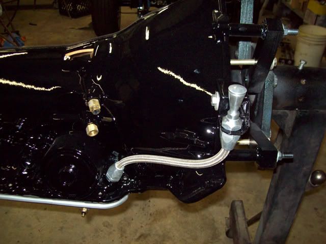
I installed the dip stick too. It's a Lokar unit, but I had to fab a new mount. The original mount was going angle it up toward the headers. The new mount puts it vertical near the firewall.
I hope to get the shifter on next week.
-
12-07-2008 05:45 PM #2
CHR Member
- Join Date
- Feb 2007
- Location
- Vidalia
- Car Year, Make, Model: 1946 Ford Coupe, 1962 Austin Healey 3000
- Posts
- 1,508
Now it time to talk about a little technical problem I created for myself.
Warning: This is very long post!!!(for me at least)
Anytime you make changes to a build after you're well along in the construction, you're subject to create problems and that's just what happened here. I do want to add that I'm not an engineer and this is just a long story about what I did to my car. I'm not going to tell you this is what you should do (only you can decide that).
I started this build with GM metric disc brakes on the front and S-10 drum brakes on the rear. Since these components were designed to work together by GM, they would have been a pretty good setup. The problem cropped up when I swapped the repro 39 Lincoln drum brakes on the front.
Now I had huge relatively low pressure 12" brakes designed to stop 2+ tons of Lincoln (with no booster) on the front and 9 1/2" brakes on the rear designed to work in a high pressure boosted disc brake system. The front wheel cylinders were 1 1/8" bore, the rears were 3/4" bore and the master cylinder was 1" bore. Throw in a pretty good difference in rubber size and it was obvious that I had a bad mismatch. I figured that with the boosted master cylinder and self-energizing drums front and rear, the brakes were going to be overly sensitive and the fronts were going to be locked up before the rears ever got enough line pressure to do anything meaningful.
My first thought was to swap to bigger drums on the rear. That would have easily solved the brake mismatch issue, but would have added a lot of unsprung weight to an already heavy rearend. T's don't have a good sprung/unsprung weight ratio anyhow and I didn't want to make it worse by adding more weight. Besides, the S-10 drums and other parts I had were in perfect shape. All I really needed were new wheel cylinders. So, I looked at other options.
I decided to do a little research on drum brake systems from back when they were pretty much the only game in town to see how they were setup from the factory. The NAPA website lists the bore sizes of brake parts, so I spent some time checking out brake specs for several cars and trucks from the 50's and 60's. I did notice a pattern (sort of) in the sizes of parts. I say "sort of" because there are always exceptions. The front wheel cylinders and master cylinders were generally the same or nearly the same bore. Manual brakes had slightly larger wheel cylinders on the front, while power brakes got pretty much the same size as the master. The rear cylinders were about 20% smaller (by area) on trucks and 10-15% smaller on cars.
Using my research as a guide, I looked for a better combination of parts. Since my master cylinder is 1" bore and has a booster, I looked for some 1" bore wheel cylinders for the front. A late 60's Buick 225 has 12" brakes (turns out that didn't really matter) and 1" wheel cylinders on the rear that matched the castings and port locations of the Lincoln brakes I was using. They were a direct bolt-in replacement and brought me in line with my research.
The rear wasn't quite as easy, though. The rear cylinders are of a much later design than the fronts and had a unique setup. The pistons and the extensions that push on the shoes are one piece. The only wheel cylinders I could find that were larger and had those pistons were from a 90's model Astro van. They were 7/8" bore. That's still almost 30% smaller than the fronts. It was time to go to plan B.
I found that an early 80's Caprice had 15/16" bores, the same port layout and bolt spacing, but of course the pistons were wrong and the machined locating boss was 1/8" too big. Hey, that's no problem since I have a lathe and I'm not afraid to use it!
I fabbed up some new steel pistons with the correct shape and size. I also turned the wheel cylinder boss down and pushed the shoulder back to get the center line of the bore back where it needed to be.
These new cylinders are 19% smaller than the fronts and that's a lot closer to my research. Not as good as I had hoped, but in the ballpark. The next size up would be 1", but I don't want to worry about locking up the rear wheels first on slick roads (or dry roads for that matter).
I could have left the 1 1/8" cylinders in the front and went with 1" cylinders in the rear (modified 85 Chevy truck), but I would have had to change the master cylinder to a 1 1/8" unit. That would have given me a 14% difference, but the master cylinder costs more than the wheel cylinders.
I'm going to leave it as it is for now and see how it works. I can always make changes later. Since the new rear cylinders have an area that is 36% larger than the old units, there's no doubt that these mods will improve the effectiveness of the rear brakes. The smaller front cylinders should make the front brakes less sensitive. The only problem will be if I created a premature lockup problem in the rear (that won't be good!). I'm not overly concerned about that because the difference in drum and tire sizes still has the rear brakes at a disadvantage. Time and testing will tell, but I'm moving on to other parts of this project for now.
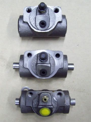
Top cylinder is the stock Caprice unit, bottom is the stock S-10 and the middle one is my new hybrid.
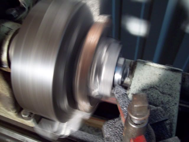
Just a little action shot of the lathe work.
-
12-07-2008 07:24 PM #3
CHR Member
- Join Date
- Jul 2003
- Location
- Titusville, FL
- Car Year, Make, Model: 31 Ford Coupe; 32 Ford 3-window
- Posts
- 1,793
I have never done such thorough research on brakes, so I may be completely wrong, but it looks like you've got things pretty close now. Anyway, if it turns out that you still end up with too much pressure on the rear, can't you just put an adjustable proportioning valve (like we use in stock cars) in the rear line?
Jim
Racing! - Because football, basketball, baseball, and golf require only ONE BALL!
-
12-08-2008 01:29 AM #4
CHR Member
- Join Date
- Feb 2007
- Location
- Vidalia
- Car Year, Make, Model: 1946 Ford Coupe, 1962 Austin Healey 3000
- Posts
- 1,508
JR
I already have a proportioning valve plumbed in. I put it in when I still had the discs on the front just in case I needed it.
BTW Your car is looking great!
Mike
-
12-28-2008 06:04 PM #5
CHR Member
- Join Date
- Feb 2007
- Location
- Vidalia
- Car Year, Make, Model: 1946 Ford Coupe, 1962 Austin Healey 3000
- Posts
- 1,508
 It's going back together!!
Now that Christmas is over, I thought I would take time to post an update. I hope everyone had a good holiday.
First things first, though. I have to make a correction to an earlier post.
Turns out that my math was off in my post about the wheel cylinders. The 1 and 15/16 combo Im using actually gives me a 12% difference instead of the 19% figure that I posted.
The 1 1/8 and 1 combo would actually be 21% difference.
I had refigured everything for my post and dont even know where I got those numbers. Must have left my brain somewhere else that day!
Sorry if I caused anyone to be confused.
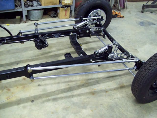
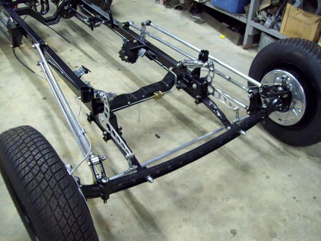
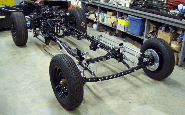
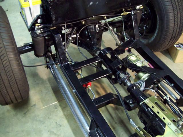
The frame front and rear suspensions have been assembled and squared. I still need to set the pinion angle and the caster on the front end. Im waiting until the engine is in for this step. I can go over all the bolts then and make sure they are tightened and locked.
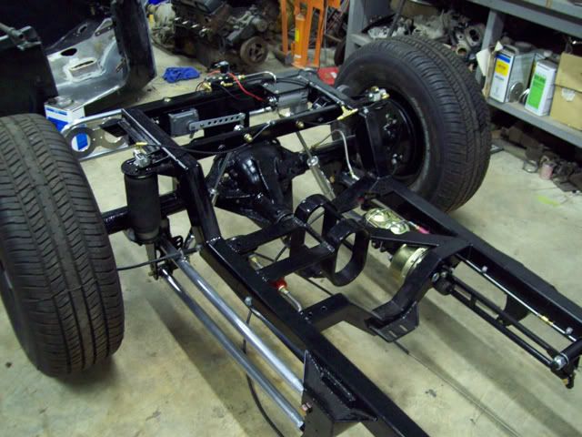
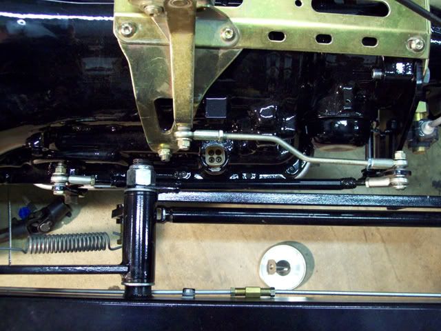
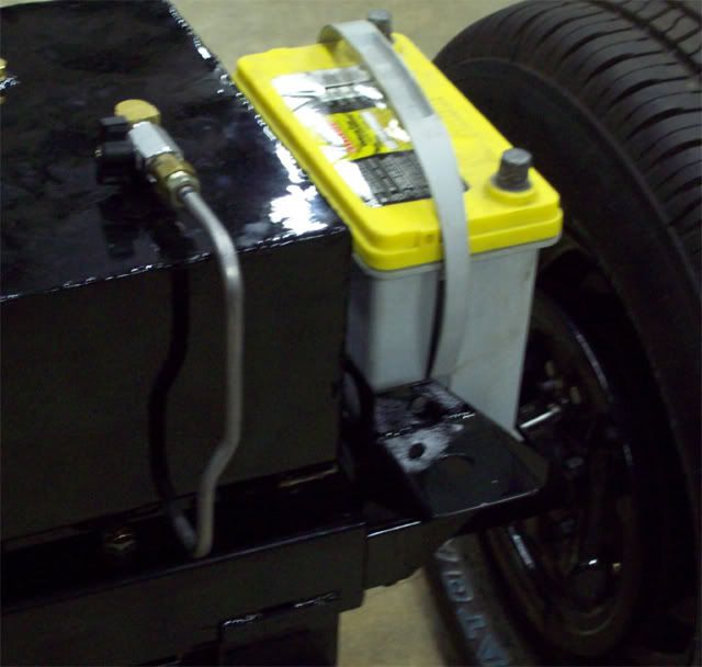
The air compressor, valves and air bags are all mounted and plumbed. The valves are small 1/8 stainless steel units, but they're big enough for what I'll be using them for. I mounted a valve directly to each bag using solid pipe fittings to keep the two sides of the car separate. Each bag will be a separate "spring", so there shouldn't be any air transfer from bag to bag when the car leans. Should also help keep any small leaks at the tubing connections from bleeding the bags down overnight since they're essentially sealed. It has been aired up for about 2 weeks now and doesnt appear to have leaked down.
When I was testing this setup earlier in the build, it only took about 30-40 lbs. of air to hold the car at ride height with one person on board. I would be surprised if it took more than 50-60 when it was fully loaded. Each bag has an 800 lb rating at 100 PSI. There is one valve with a restrictor mounted on an aluminum manifold to bleed off air, so only 3 valves are needed for the whole system. There is no air tank; the air compressor will push air directly into the bags. During earlier testing, the compressor took only a few seconds fill the bags if they were empty. There is a safety switch on the distribution manifold that will kill the compressor if the system gets to 105 PSI.
Im using a GM control switch to keep the ride height where I want it. These were used on high end GM cars in the 70s through the 90s. They are not much bigger than a pack of cigarettes and attach to the frame. An arm and linkage attaches to the rearend. The length of the link determines the ride height. Not as sophisticated as the programmable controllers on the market today, but theyre usually cheap and as close as your local junk yard. Add a couple of automotive relays and youre good to go.
Hard to see in the pics, but I rounded the ends of the leaf springs to make them look a little better. I also added a third leaf to the front spring packs. I didnt feel real confident about using just two leafs. These are heavier ¼ thick leafs.
I spent a lot of time chasing threads and fitting parts where they were powder coated. Note to self: Dont build this stuff so tight if youre going to powder coat it! The ceramic coating is aluminum based, so I used liberal amounts of anti-seize compound. I didnt want to risk galling the threads.
The brakes are bled, but not without some problems. I had a new wheel cylinder leaking!! No, it wasnt one of the modified cylinders. It was one of the new ones I bought for the front. I pulled it apart and found that it was full of crap that looked like kitty litter. Nothing was damaged, but the crud had gotten under the cup lips and wasnt allowing it to seal. After cleaning it up everything was fine, but I use a pressure bleeder and it sure made a heck of a mess before I saw it was leaking. I hate to think that Im going to have to start pulling NEW parts down and check them before I use them. More of that good Chinese crap!
All of the hard fuel lines, the fuel pump and filter are installed. I still have to make up the braided flex lines for the fuel system.
The engine and trans is going in tomorrow.

-
01-06-2009 08:01 PM #6
CHR Member
- Join Date
- Feb 2007
- Location
- Vidalia
- Car Year, Make, Model: 1946 Ford Coupe, 1962 Austin Healey 3000
- Posts
- 1,508
I got a lot accomplished on my days off over the holidays.
The shifter is on and the linkage is finally worked out. I wound up fabbing the long link out of ½ steel tubing, since the all-thread Lokar provides wasnt stiff enough when bent to clear the brake pedal.
The engine and trans are together and in the frame.
The alternator is back together and installed on the engine. Same with the fan, pulleys and belt.

I reprimed the oil pump (just to be sure), reinstalled the distributor and retimed the engine to 10 degrees BTDC.
The body had to be dropped back on (temporarily) to check the routing of the spark plug wires around the steering shaft. I had to make up a couple of mounts for the Made For You looms Im using, but the wires tuck in nice under the headers AND clear the steering.
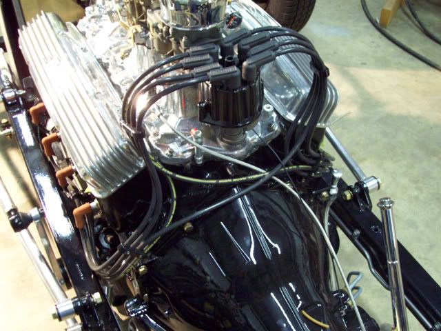
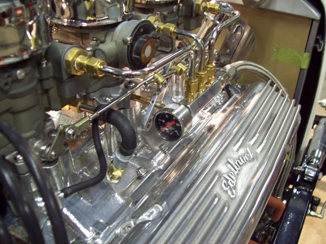
The fuel pump and filter unit went back on with all of the plumbing. I made up the braided hose that runs from the regulator to the fuel manifold on the engine. Im using a regulator because these 2Gs dont need more than 4-4½ PSI. I also drilled the rear of the fuel manifold and installed a fuel pressure gauge.
After running the hard line from the tank to the pump, I realized that I wouldnt be able to pull the tank with the body on. I had to add a coupling so that the upper bend could be removed.

The trans cooler lines are back on and the transmission throttle valve cable (Lokar) is installed. I got lucky because the trans cable stud on the throttle arm was pretty close to where it needs to be for a 700R4. If youve never used a 700 before, you need to know that the location of that stud is very important. It needs to follow a specific radius as the throttle is opened or you can burn your trans up. That info can be found here:
http://purplesagetradingpost.com/sum...o/700R4p1.html
The driveshaft is assembled, installed and the pinion angle is set. On the front I set the caster angle at 6 degrees.
The emergency brake cables are hooked up and partially adjusted. I left them a little loose for now because the handle needs to be straight up for the body to go on. When the body is bolted on, Ill give it the final adjustment.
I also moved the body to a location in the shop where I can get started on the sanding and body work. If the weather permits next week, I may start on some of that. I can always work on the frame while its cold, but the paint likes the weather a little warmer.
Because I tend to work slower than Christmas, I have hesitated to set a firm time goal for getting this thing on the road, but there are two shows in March that I would really like to take it to. I figure I can make it pretty easily, but Im going to have to paint when I can. Might not have any interior, though.
When my off time ran out, I was working on final fitment of the radiator, shell and plumbing.
Mike
-
01-06-2009 08:14 PM #7
CHR Member
- Join Date
- Jan 2006
- Location
- fort myers
- Car Year, Make, Model: '27 ford/'39 dodge/ '23 t
- Posts
- 11,033
Mike, I have been watching this car come together since the beginning and really really like the way it looks and the way you are doing it. Everything just looks so right, and now that you are getting all of the paint and shiny stuff on it looks spectacular. You are down to the short strokes now bud.
I agree with Jim, the proportioning valve should take up any mismatch. I have 12 inch 46 Ford brakes with Buick drums on the front and S10 9 or 10 inchers on the back, with a Mustang master cylinder. It balanced out fine, so I think you will be ok too. The lightweight of these cars helps a lot too.
I've looked at your latest pictures several times and find new stuff every time I do...........very interesting, cool car. Get er done.........you are near the finish line.
Don
-
01-08-2009 02:28 AM #8
CHR Member
- Join Date
- Jul 2003
- Location
- Titusville, FL
- Car Year, Make, Model: 31 Ford Coupe; 32 Ford 3-window
- Posts
- 1,793
Wow! What a cool idea for your PCV system. With everything else in place, it practically disappears. I would never have thought of that if you gave me the parts and a year to think about it.
") I'll definitely file that one to the "memory banks".
I'll definitely file that one to the "memory banks".
The whole thing is really looking good, Mike. What is the intended paint scheme for the body?
Jim
Racing! - Because football, basketball, baseball, and golf require only ONE BALL!
-
01-08-2009 05:41 AM #9
CHR Member
- Join Date
- Nov 2007
- Location
- Bonita Springs
- Car Year, Make, Model: 23 Ford T, 2004 ZO6 Vette, 99 Mustang
- Posts
- 542
Great looking car! Awesome attention to detail and I love all of you "trick" engineering. Looks fantastic! Don Jr.Don Jr.
"Once again I have thoroughly disgusted myself"
-
01-08-2009 07:40 AM #10
CHR Member
- Join Date
- Feb 2007
- Location
- Vidalia
- Car Year, Make, Model: 1946 Ford Coupe, 1962 Austin Healey 3000
- Posts
- 1,508
Thanks guys!
Tech - I was using piston area to figure the percentage. 15/16" = .69029 square inches and 1" = .7854 square inches .69029/.7854 = .8789 1-.8789 = .1211 or 12% of the area. I used area because that is what is actually doing the work. Good to know someone is interested enough to check up on me! I did spend a little TOO much time reading Hot Rod mags in math class. Miss Terry said that would catch up with me one day!
MikeLast edited by Hotrod46; 01-08-2009 at 07:43 AM.
-
01-08-2009 08:51 AM #11
CHR Member
- Join Date
- Feb 2007
- Location
- Vidalia
- Car Year, Make, Model: 1946 Ford Coupe, 1962 Austin Healey 3000
- Posts
- 1,508
JR
Sorry, I intended to answer your paint question in my earlier post, but CRS kicked in.
I'm going to keep the black on black theme going. Straight black PPG single stage. I've got a lot of sanding and priming to do!
There is a good pin striper about 2 hours from my house and I've been intending all along to get him to lay down some lines when it's all done. Probably some "Von Dutch" type stuff similar to what Don had put on his.
The interior color is still up in the air. Probably a darker red color like oxblood or deep maroon. I've even thought about black, but that might be too much black. I'd love to go with a "distressed" type of vinyl, but don't know if it's available in marine grade material.
MikeLast edited by Hotrod46; 01-08-2009 at 05:51 PM.
-
01-08-2009 11:18 AM #12
CHR Member
- Join Date
- May 2003
- Location
- Zephyrhills, Florida, USA
- Car Year, Make, Model: '32 Henway
- Posts
- 12,423
You're correct. I should resist writing this stuff in the wee hours of the morning. Originally Posted by Hotrod46


Last edited by techinspector1; 01-08-2009 at 11:21 AM.
PLANET EARTH, INSANE ASYLUM FOR THE UNIVERSE.
-
01-18-2009 06:41 PM #13
CHR Member
- Join Date
- Feb 2007
- Location
- Vidalia
- Car Year, Make, Model: 1946 Ford Coupe, 1962 Austin Healey 3000
- Posts
- 1,508
Milestone!
I have reached a very important milestone in this project!!!
IT IS ALIVE!!!!!
The engine runs!!! Sorry, but I got so involved (and a little rushed), that I completely forgot to take video.
A couple of good friends (thanks John and Jimmy) got a set of old T bucket headers to me that I used for a temporary exhaust.
Initial fire-up didnt happen without a problem or two. Self inflicted of course. I completely forgot that the oil pressure sending unit was not installed and merrily cranked away while setting the pre start-up timing. Made quite a mess!
It still needs a little tuning, but the oil pressure is good (60 PSI), vacuum is good (18-20 inches), the transmission seems to work and nothing mechanical makes any bad noises. Had a couple of minor leaks, but thats to be expected. The cam has mild specs, so it doesnt have a lot of lope, but I kind of expected that.
It sure does feel good to hear it run! 2 ½ years to get to this point. I NEVER thought it would take so long.
I ran out of time and have to go back to work (gotta pay the bills), so itll be another week before I can get anything else done.
Mike
-
01-18-2009 07:08 PM #14
CHR Member
- Join Date
- Apr 2001
- Location
- Salado
- Car Year, Make, Model: 32, 40 Fords,
- Posts
- 10,898
Can't imagine anyone else on here has ever done that!!! Originally Posted by Hotrod46
Sounds like a good day though!Your Uncle Bob, Senior Geezer Curmudgeon
It's much easier to promise someone a "free" ride on the wagon than to urge them to pull it.
Luck occurs when preparation and opportunity converge.
-
01-19-2009 04:23 PM #15
CHR Member
- Join Date
- Oct 2007
- Location
- Littleton
- Car Year, Make, Model: 31 ford five window
- Posts
- 156
No pics.... Never happened!
We are awaiting proof!!!!
p.s. Good Job!Scott
31 Ford five window
 Reply With Quote

Posting Permissions
- You may not post new threads
- You may not post replies
- You may not post attachments
- You may not edit your posts

This site is up more often lately, but very little traffic.
Dead!