


 176Likes
Thread: New Project


Results 46 to 60 of 109
 LinkBack URL
 About LinkBacks
-
03-18-2024 06:56 PM #46
 CHR Member

- Join Date
- Mar 2013
- Location
- Seguin
- Car Year, Make, Model: 1940 Ford p/u 1937 Caddy Coupe
- Posts
- 782
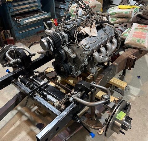
started looking at engine install today, Have to find out what fits where, clearances and routing of everything .
-
Advertising

- Google Adsense
- REGISTERED USERS DO NOT SEE THIS AD
-
03-18-2024 07:30 PM #47
CHR Member
- Join Date
- Nov 2016
- Location
- rocklin
- Posts
- 656
Subframe looks great, going to be a nice drivetrain!
-
04-11-2024 09:28 AM #48
CHR Member
- Join Date
- Apr 2011
- Location
- Prairie City
- Car Year, Make, Model: 40 Ford Deluxe, 68 Corvette, 72&76 K30
- Posts
- 7,301
- Blog Entries
- 1
Very nice work on the Caddy!Ryan
1940 Ford Deluxe Tudor 354 Hemi 46RH Electric Blue w/multi-color flames, Ford 9" Residing in multiple pieces
1968 Corvette Coupe 5.9 Cummins Drag Car 11.43@130mph No stall leaving the line with 1250 rpm's and poor 2.2 60'
1972 Chevy K30 Longhorn P-pumped 24v Compound Turbos 47RH Just another money pit
1971 Camaro RS 5.3 BTR Stage 3 cam, SuperT10
Tire Sizes
-
04-13-2024 07:11 PM #49
CHR Member
- Join Date
- Mar 2013
- Location
- Seguin
- Car Year, Make, Model: 1940 Ford p/u 1937 Caddy Coupe
- Posts
- 782
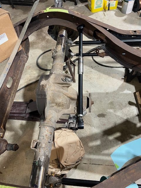
Ok guys I'm looking for input on my Panhard Bar setup. I'm mostly concerned with the mount I'm making for the rear attachment. I used 2 x 3 tube with .120 wall thickness. 1 " tube all the way through with a 5/8" bolt in that. I most likely will box in the 2 x 3 with studs sticking out to bolt to the axel. Having never built a car with parallel bars I'm not sure how strong the Panhard bar needs to be ? Thoughts ?
Is this location good in relation to the rear axel/ most I've seen are above the center line of the axel.
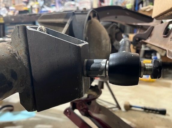
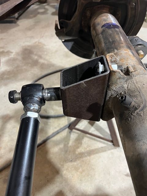
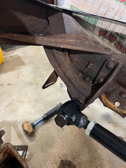
This pic is of the mount on the car, not sure what it used for in 1937 but it seems to be right for the bar attachment to the frame.
thanks for your inputs !!Last edited by Navy7797; 04-13-2024 at 07:15 PM.
-
04-14-2024 03:26 AM #50
CHR Member
- Join Date
- Sep 2007
- Location
- New Bedford
- Car Year, Make, Model: 34 Ford 3W Coupe Replica
- Posts
- 14,754
Like you I'd be concerned with the box tubing, that's quite a distance from axle mount to the bar mounting. I like the idea of changing the bolts too, come through the box with bolts and weld the head of the bolt in the box. If needed, you could perhaps add a mount from the box to the axle tube and it would triangulate and spread the loading. Otherwise, I'd add some bends to the long tubing and shorten the axle mount.
-
04-14-2024 06:36 AM #51
CHR Member/Contributor
- Join Date
- Sep 2007
- Location
- Gardner, KS
- Car Year, Make, Model: '33 HiBoy Coupe, '32 HiBoy Roadster
- Posts
- 11,245
My panhard bar on on both cars are from Pete & Jakes, mounted from drivers frame to two bolts holding the third member to the differential housing and two bolts holding the pinion shaft to the third member. I think the brackets to hold the heim are 1/4" - they are stout! The longer the bar the less lateral movement you get as the differential travels up & down, but the longer bar has more flex. In an easy swale where you're going straight there's not much force on the panhared bar, but consider a twisty hill country road where you're pushing the suspension to max G forces in a downhill S turn. You're putting the panhard bar in compression, then tension while going through a mid-turn dip that's trying to break the rear loose. Also, consider that as the differential travels up & down it moves fore & aft a bit in the arc of the parallel arms.Your panhard mounts are going to see those forces and have to be strong enough to put that movement into the bar flex, not the mount or the mounting bolt. Both ends of your bar rely only on the mounting bolt through the heim, in flex.
Your mount needs to be close coubled to the axle flange, and I would extend it above the axle tube an inch or so but I'd be very concerned with a single side mount that puts all of the force on the bolt through the heim. It needs to be supported on both sides so the bolt is only in shear. Same on the frame end, you need two plates welded to the frame solid to carry the heim. That existing frame mount won't last 50 miles,IMO. How about using a flat plate on the existingg axle mount, extending up with a second shorter flat plate welded to the tube spaced to fit the heim insert? Att the frame, makje a pair of triangle plates, rounded at the top, welded to the frame rail spaced for the heim insert. That would put your Grade 8 bolts in shear, and would be plenty stout!!
Here's a picture of one of Pete&Jakes panhard bar kits for reference - https://www.peteandjakes.com/parts/p...d-stock-width/Last edited by rspears; 04-14-2024 at 08:01 AM.
Roger
Enjoy the little things in life, and you may look back one day and realize that they were really the BIG things.
-
04-14-2024 08:48 AM #52
CHR Member
- Join Date
- Mar 2013
- Location
- Seguin
- Car Year, Make, Model: 1940 Ford p/u 1937 Caddy Coupe
- Posts
- 782
I see what your saying about the support of the Heim joint needing to be on both sides , thanks ! Originally Posted by rspears

-
04-14-2024 10:12 AM #53
CHR Member
- Join Date
- Mar 2013
- Location
- Seguin
- Car Year, Make, Model: 1940 Ford p/u 1937 Caddy Coupe
- Posts
- 782
OK here's another look at the bar mounting
bar to be located in this area with tabs on each side to support the heim joint
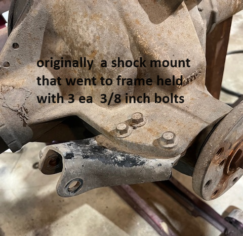
Here is a pic of the rear where a shock was mount off to the frame (rear had leaf srings originally) Planning on fabricating off this point.
Thoughts ?
-
04-14-2024 11:33 AM #54
CHR Member/Contributor
- Join Date
- Sep 2007
- Location
- Gardner, KS
- Car Year, Make, Model: '33 HiBoy Coupe, '32 HiBoy Roadster
- Posts
- 11,245
I'd mount the heim between the shoulders of that mount, or fabricate a new piece to fit using those mounts with Grade 8 bolts, but with the bar running to the passenger frame rail so it doesn't have to cross the third member snout. The problem on the frame end is that your heim needs to swing up and down for suspension travel, not front to back. Fabricate a pair of mounts to weld up towards the top of the frame, inside the C section, or even tabs that weld to the inside at the corner, top and outside surfaces.Last edited by rspears; 04-14-2024 at 11:39 AM.
Roger
Enjoy the little things in life, and you may look back one day and realize that they were really the BIG things.
-
04-14-2024 02:10 PM #55
CHR Member
- Join Date
- Mar 2013
- Location
- Seguin
- Car Year, Make, Model: 1940 Ford p/u 1937 Caddy Coupe
- Posts
- 782
rspears Thanks for the input ! I looked at that and when I measured the amount of rear side travel it was 7/16"and with the long bar its 1/8". This is going air ride on all corners with movement of 4" total, that's what I did the measurements from for side movement. Trying to keep bar parallel with the rear at ride height its all a pita.
-
04-14-2024 02:50 PM #56
CHR Member/Contributor
- Join Date
- Sep 2007
- Location
- Gardner, KS
- Car Year, Make, Model: '33 HiBoy Coupe, '32 HiBoy Roadster
- Posts
- 11,245
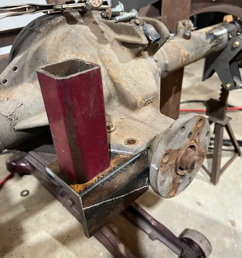
Navy, how about fabricating a new "shock mount" with a ~3/8 flat plate and a 3 sided extension, maybe a chunk of 2"x1/4 wall square tube to put your third member mount higher to clear the snout, and get your panhard bar closer to level at ride height. Mount the frame end at the bottom of the C channel, welding to both bottom and side. You could even add a couple of gussets to the square tube for stiffening, or use heavy wall C channel or rectangular tube. The 2" might have to be 2.5" or 3" to clear the heim insert. Just some quick ideas.... Originally Posted by Navy7797
Roger
Enjoy the little things in life, and you may look back one day and realize that they were really the BIG things.
-
04-14-2024 05:07 PM #57
CHR Member
- Join Date
- Mar 2013
- Location
- Seguin
- Car Year, Make, Model: 1940 Ford p/u 1937 Caddy Coupe
- Posts
- 782
Yup that's what I started this afternoon, pic's tomorrow. Thanks for your input. Originally Posted by rspears
-
04-14-2024 05:50 PM #58
CHR Member
- Join Date
- Mar 2013
- Location
- Seguin
- Car Year, Make, Model: 1940 Ford p/u 1937 Caddy Coupe
- Posts
- 782
hers's what have started for the rear mount, 3x3-3/8" angle and 2x2 -1/4 tube. Mounting bolts will be 7/16"-20 grade 8
-
04-15-2024 05:21 PM #59
CHR Member
- Join Date
- Mar 2013
- Location
- Seguin
- Car Year, Make, Model: 1940 Ford p/u 1937 Caddy Coupe
- Posts
- 782
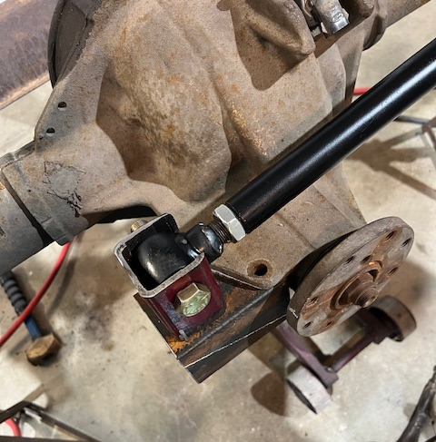
another day of fun lol, welded an 3/16 " flat piece of steel to the 2x2 tube to give me the 1.75 ID I needed for the Heim joint. Cut height to just clear the body Sheetmetal. you see where I milled out for clearance. The pic makes it look thin on that side but its 3/16- 1/4 thick.
Last edited by Navy7797; 04-15-2024 at 05:25 PM.
-
04-26-2024 06:38 PM #60
CHR Member
- Join Date
- Mar 2013
- Location
- Seguin
- Car Year, Make, Model: 1940 Ford p/u 1937 Caddy Coupe
- Posts
- 782
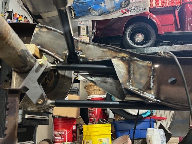
here's the latest, I had to cut up the cross section of the frame to get the parallel bars in place and these pic's show my fix .
3 x 6 tube used to rebuild the frame section.
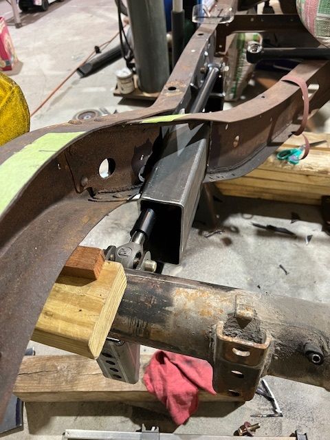
after lots of cutting and still finish grinding to come. Pic shows full upward position of travel of rear
Last edited by Navy7797; 04-26-2024 at 06:40 PM.
 Reply With Quote

Posting Permissions
- You may not post new threads
- You may not post replies
- You may not post attachments
- You may not edit your posts

This site is up more often lately, but very little traffic.
Dead!