


 6Likes
Thread: 1965 Fairlane build


Results 1 to 15 of 57
 LinkBack URL
 About LinkBacks
Hybrid View
-
02-10-2012 08:00 AM #1
 CHR Member

- Join Date
- Jun 2008
- Location
- Leonardtown
- Car Year, Make, Model: Walking
- Posts
- 1,228
1965 Fairlane build
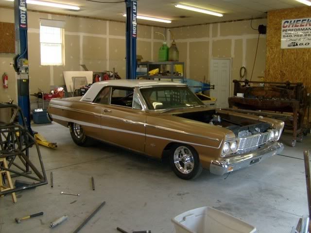
Although this car is already complete, I did take a grunch of photos, so perhaps posting a build thread here, with some of the rust repairs or other tips & tricks can help someone out for working on their own project.
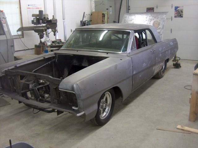
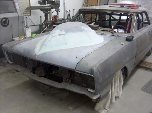
The owner first had plans for a resto-mod, but after a weekend as a spectator at the MIR drag strip, he had flashbacks of an earlier time, and the direction of the build drastically changed. A full chrome moly tube chassis was built and the body installed at Cheeks Performance in VA. And this is what I had to work with.....
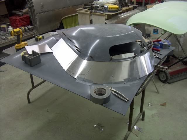
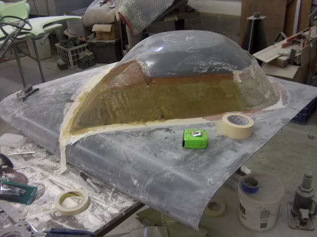
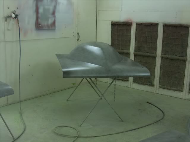
As an homage to the Thunderbolts from a year earlier, the owner had decided on a Crites teardrop hood. Only it didn't quite fit......
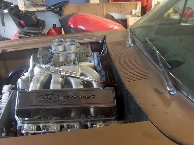
....as the engine was raised up a bit for the harmonic balancer to clear the rack and pinion. He was ready to throw in the towel and send the hood back, and concede to using a snorkel. I told him to order another teardrop, and we'd make it work. He was hesitant (I don't think he trusted me), but he did order it.
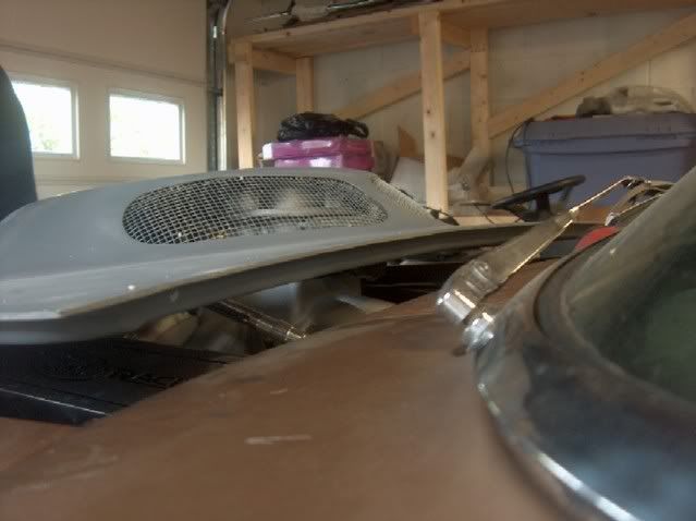
Height mocked up. The aluminum will be used to support the f/g mat while the resin cures. Then it will get flipped over, remove the aluminum, and more mat goes in from the back side. I never could get the hang of welding on fiberglass, so I had a local Corvette guy come over and join in the fun. :lol_hitti
Strips of f/g mat laid in to tighten things up, and keep the hood scoop from moving.
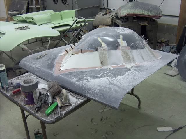

The owner did stop by and loved the look. When I gave him a hard time, he did say it wasn't that he didn't trust me, just that he couldn't see my vision.
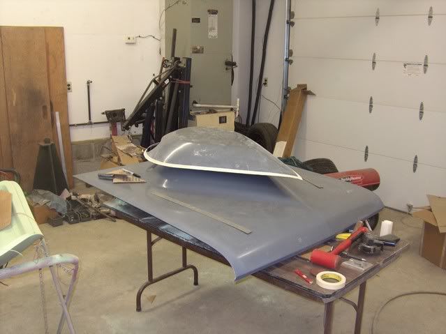
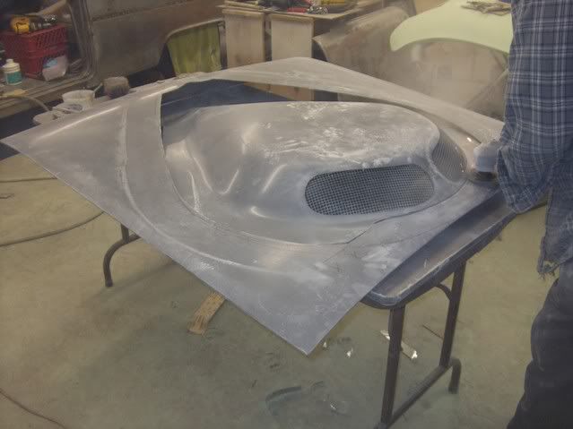
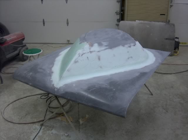
Starting to take shape. All the aluminum is removed, mat installed inside and out. A couple low spots and thin spots, as well as one really thin spot that looks like a hole!
I think this might work yet!
-
02-10-2012 08:05 AM #2
CHR Member
- Join Date
- Jun 2008
- Location
- Leonardtown
- Car Year, Make, Model: Walking
- Posts
- 1,228
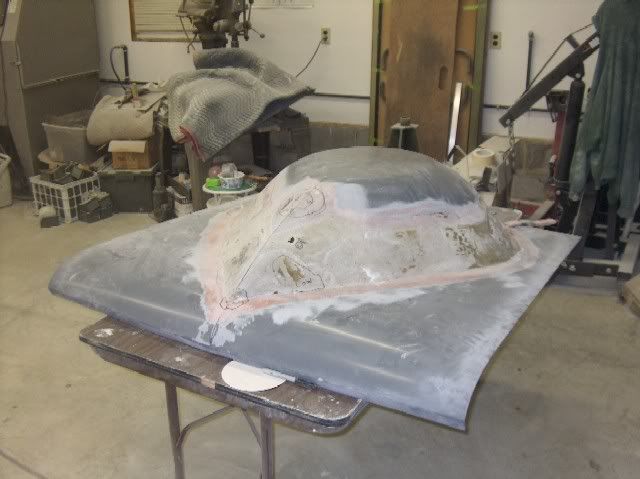
And before you say it, yeah it's rather bulbous and has been compared to Tip Oneal's nose before..
more progress on the hood.....
A final smoothing with some evercoat 416, and ready for another test fit..

Next, as I was busy working on something else, the owner decided to try his hand at sanding the paint off the body. This was about June-July time frame, the sun was mercilous on his thinning topside, and after about a week using a DA outside in the heat, he found someone to media blast it.
This showed some areas in need of repair....

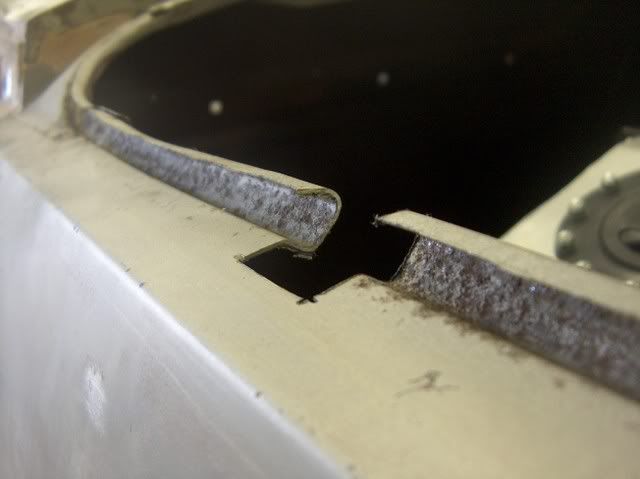
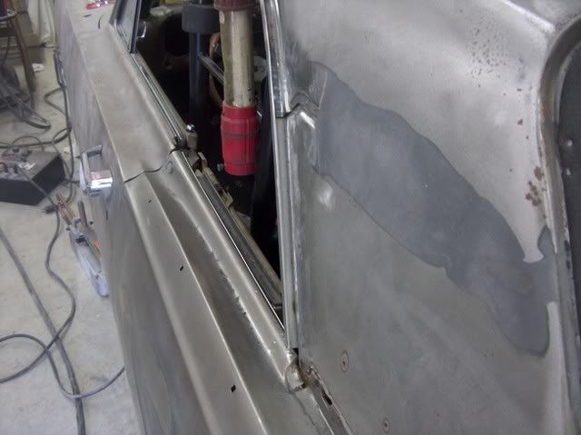
...a factory misfit (identical on two different 65's I've seen)

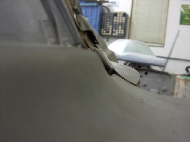
As he was anxious to go racing, he thought we should leave the door to cowl issue alone, but I assured him that a smoother, more streamlined fit would shave at least a second off his e.t.
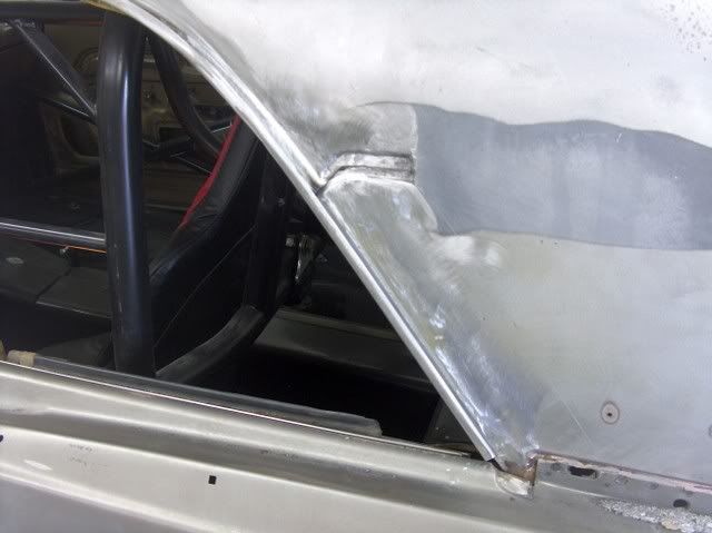
So with a little cut here, and a slight bump downward, it was fixed to where the factory should have made it....
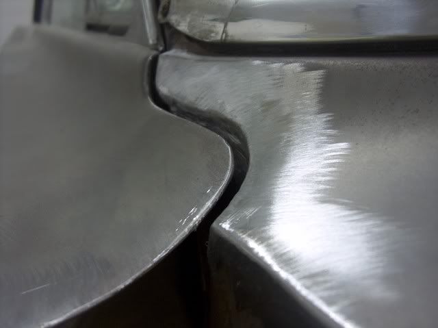
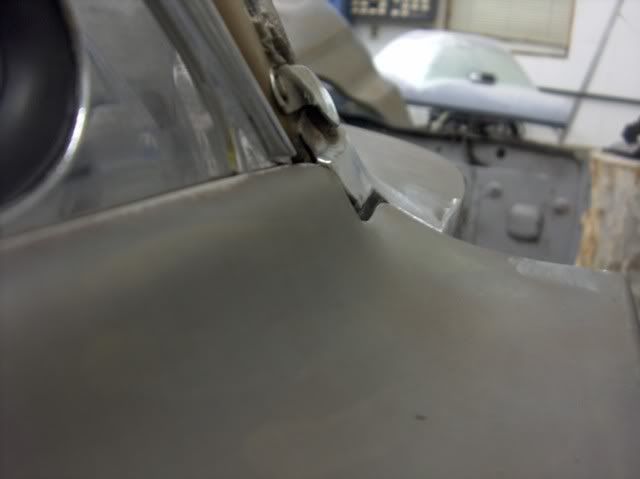
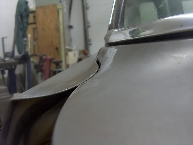
Much better.
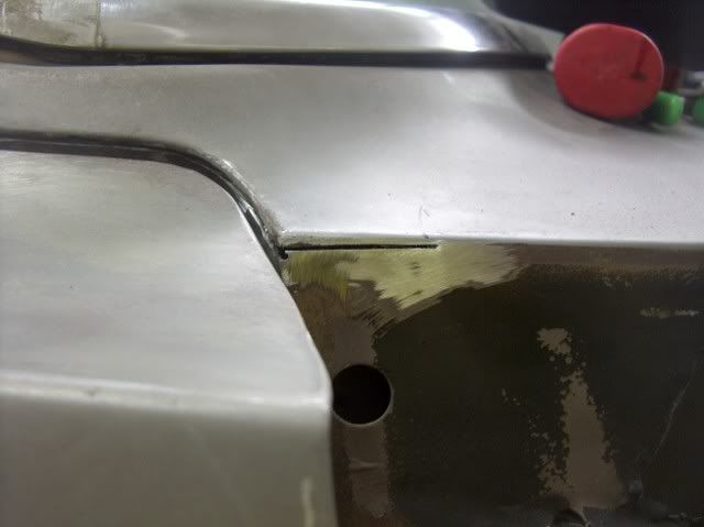
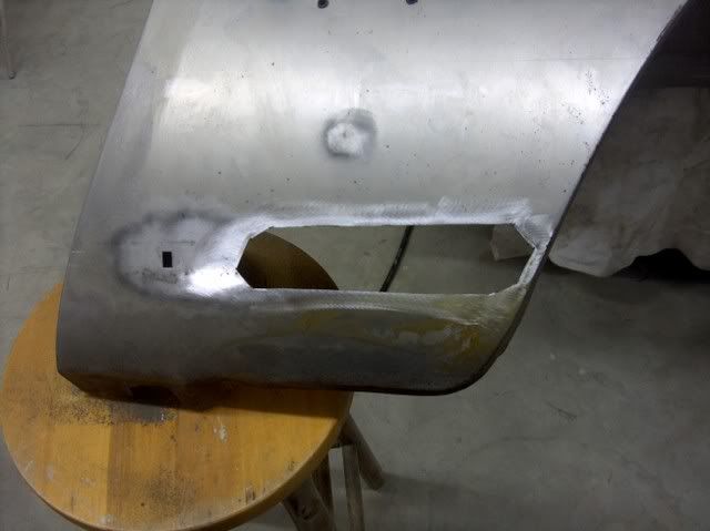
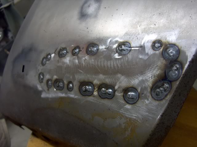
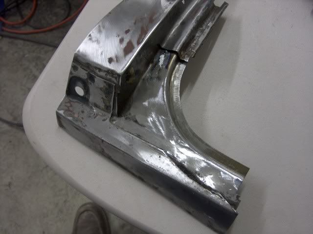
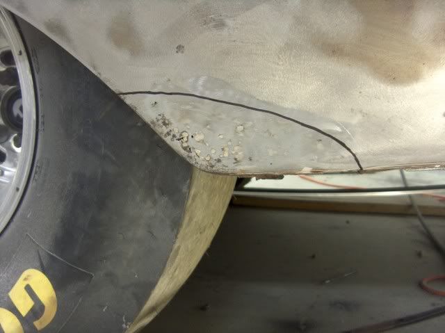
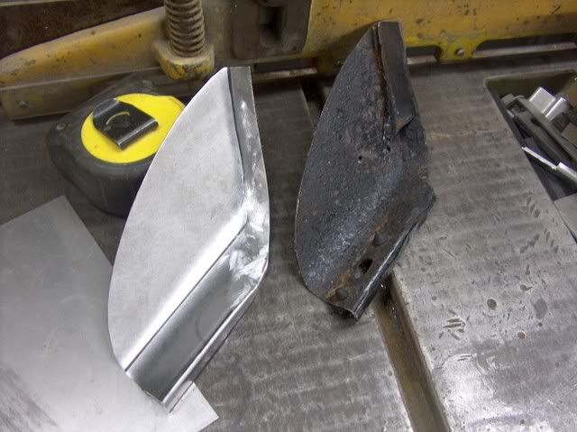
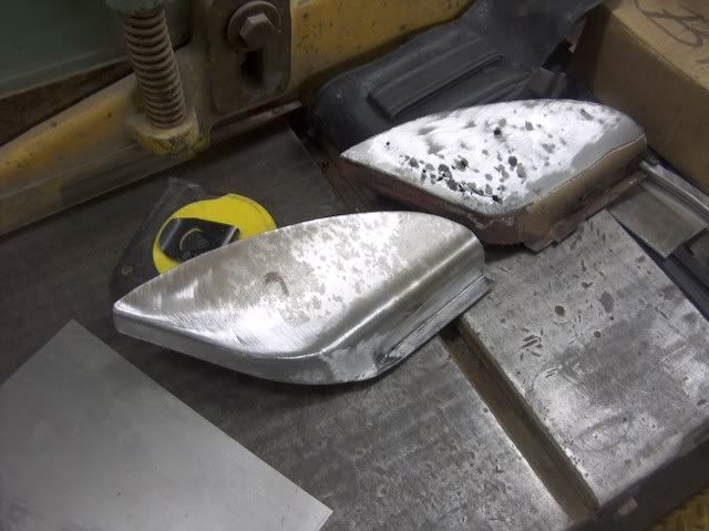
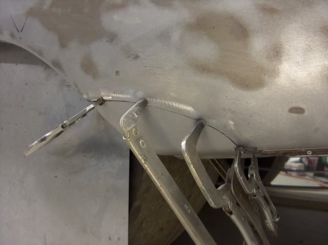
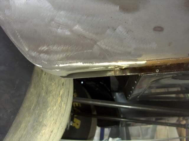
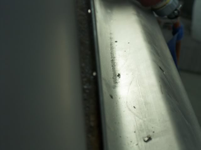
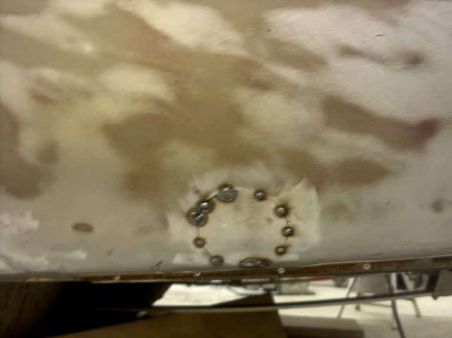
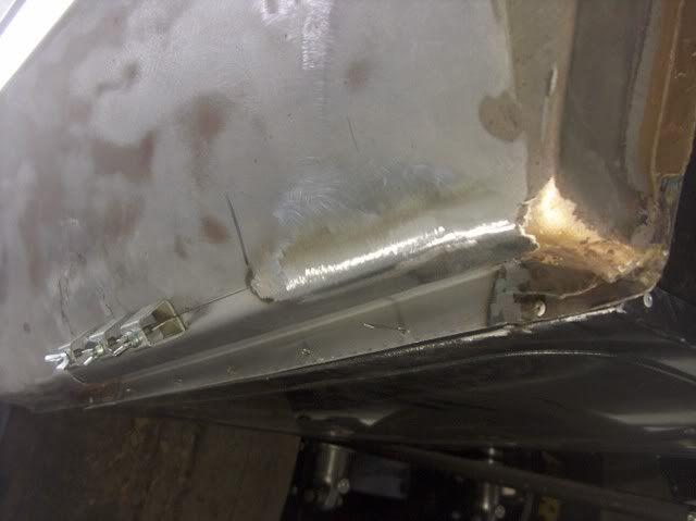
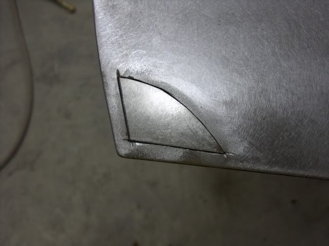
Another area that needed attention was the lower front fender where the stainless trim had served as a nice moisture trap...
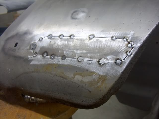
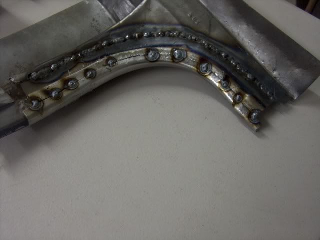
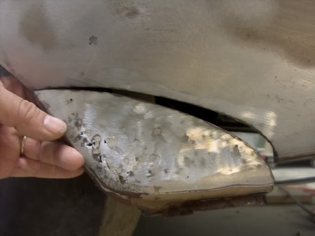
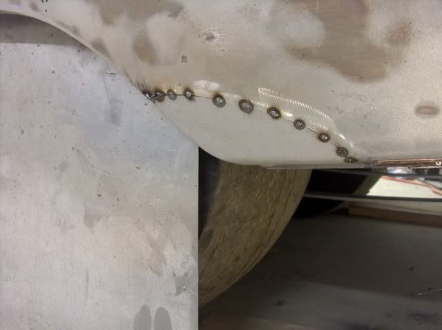
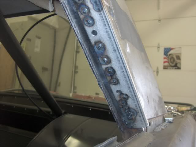
Looking at the backside, notice the full penetration on the "dot" welds. If it's just sitting on top, there won't be anything left to hold once you grind things down smooth, so always check the back side to make sure the welder is set hot enough for a full penetration weld. Then they are planished, ground down, and repeat.....


-
02-10-2012 08:08 AM #3
CHR Member/Contributor
- Join Date
- Sep 2007
- Location
- Gardner, KS
- Car Year, Make, Model: '33 HiBoy Coupe, '32 HiBoy Roadster
- Posts
- 11,245
Cool build thread, and like seeing the metal work details. I must say that the new scoop is HUGE, but the glass work is great!Roger
Enjoy the little things in life, and you may look back one day and realize that they were really the BIG things.
-
02-10-2012 08:20 AM #4
CHR Member
- Join Date
- Jun 2008
- Location
- Leonardtown
- Car Year, Make, Model: Walking
- Posts
- 1,228
Thanks, yeah it is quite the focal point, but needed to give us room around the alcohol carb...
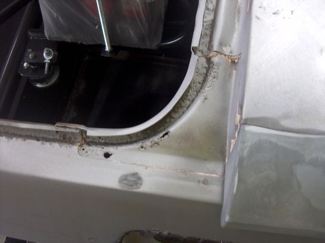
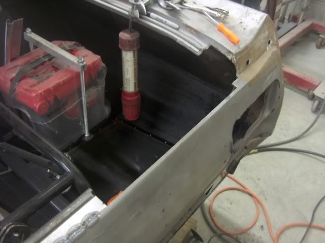
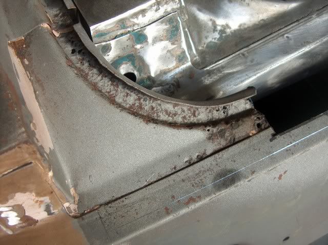
Moving back to the trunk area, the more you look the more you don't want to.
The channel for the weatherstrip seems to have sealed water in as well as out....

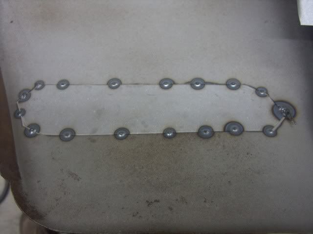
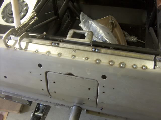
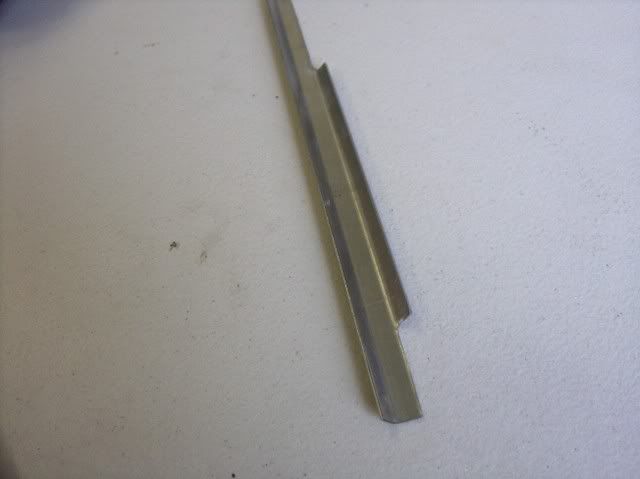
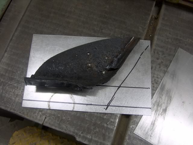
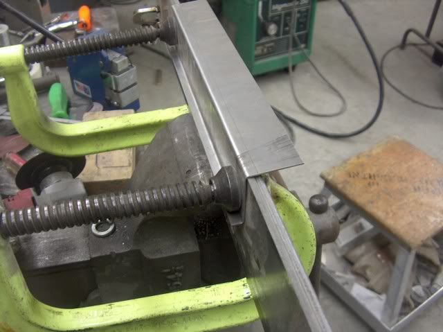
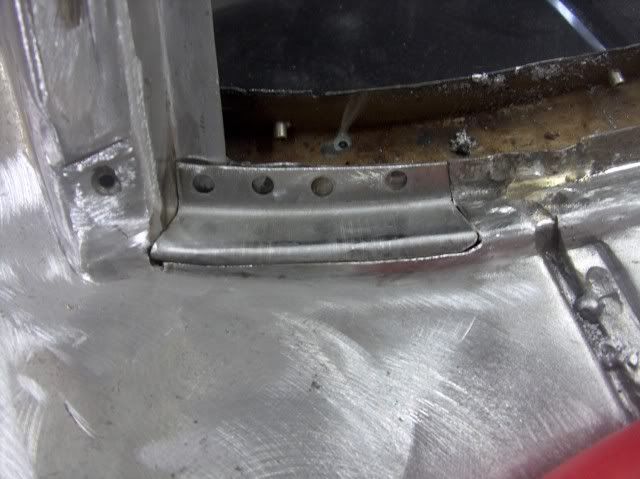
It took a few weeks and a few phone calls, but there are still some good junkyard pieces available. We got the corner pieces out of a yard in CO. The rear channel across the trunk opening also has scattered pin holes, so I though I'd give a shot to bending some new ones. First, need a template:
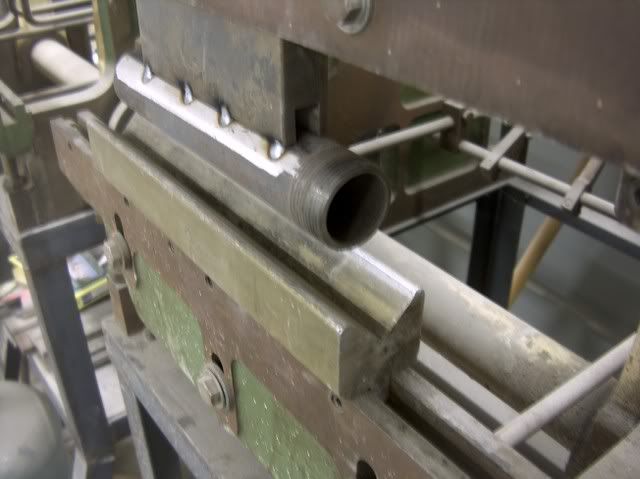
That looks close enough. My press brake dies are only about 18" long, so I'll need to do this in three pieces. The middle one got put in first.
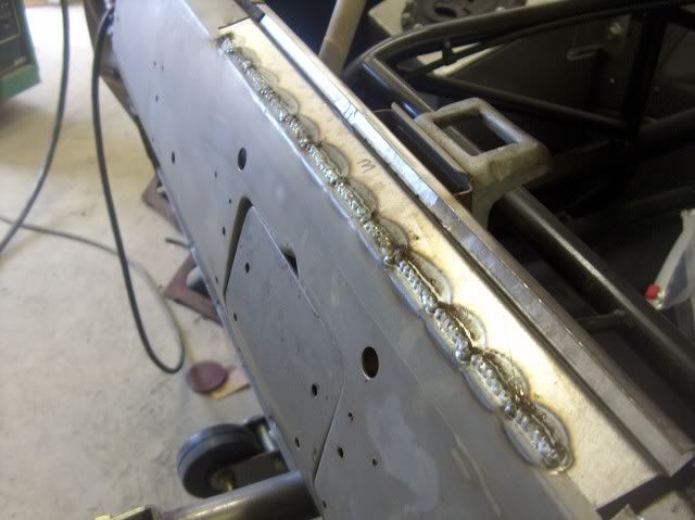
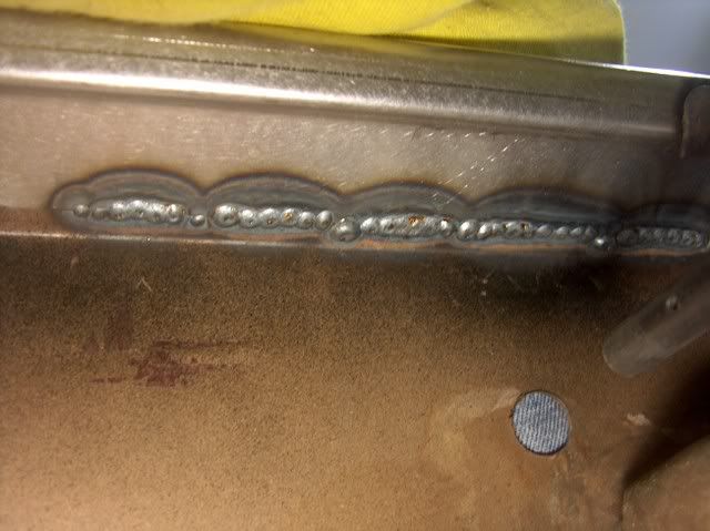
Be sure to check the back side for weld penetration:
The replacement corner was cleaned up, the spot welds were ground off of the adjacent pieces to release the corner with no damage. Looks quite a bit better than the old one.

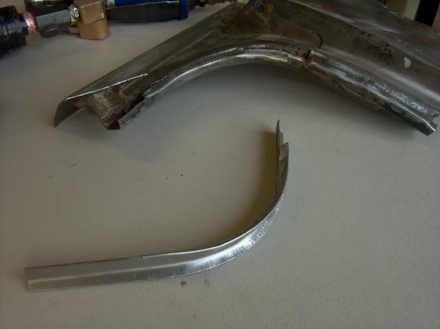
Well, on to the next corner. The driver's side was in sad shape:
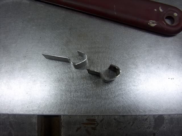
But in looking at the replacement, although in better condition, it did have issues of it's own.
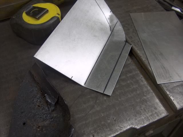
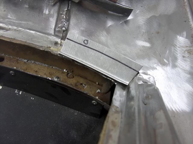
Time to break out the trusty Lancasters and make some replacement parts.
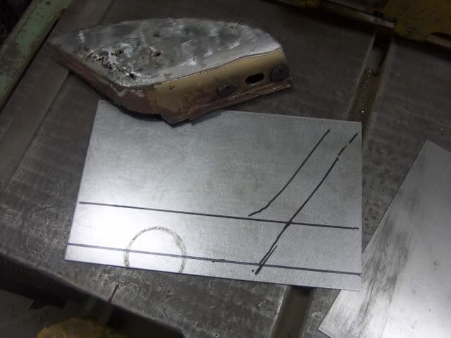
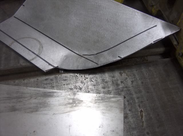
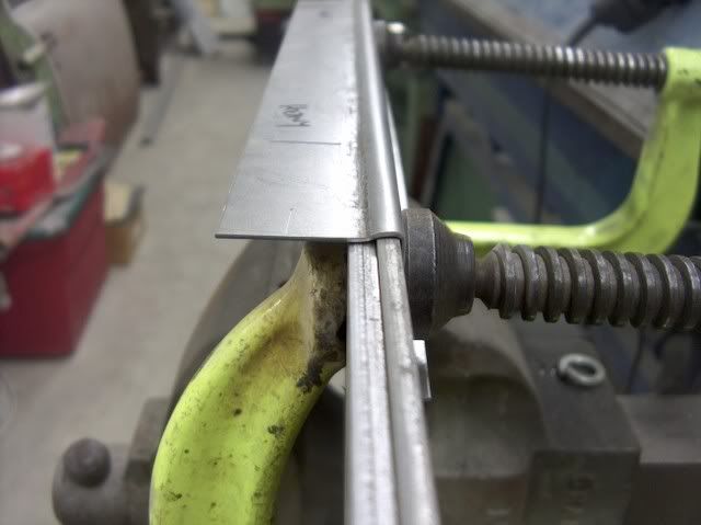
The replacement corner was left attached to the quarter panel section it came with while remaking the channel in an attempt to maintain the shape.
Note the sharpie "reference lines" in the next picture, to keep the bend in the correct location.
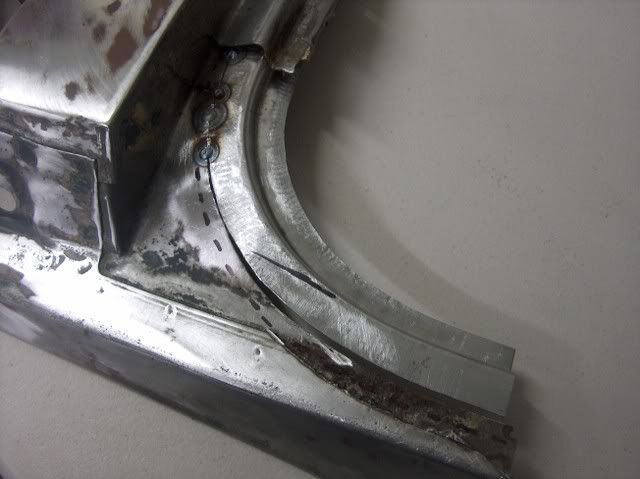

....And a comparison of the "new" part to the old one. That should do the trick!
-
02-10-2012 08:32 AM #5
CHR Member
- Join Date
- Jun 2008
- Location
- Leonardtown
- Car Year, Make, Model: Walking
- Posts
- 1,228
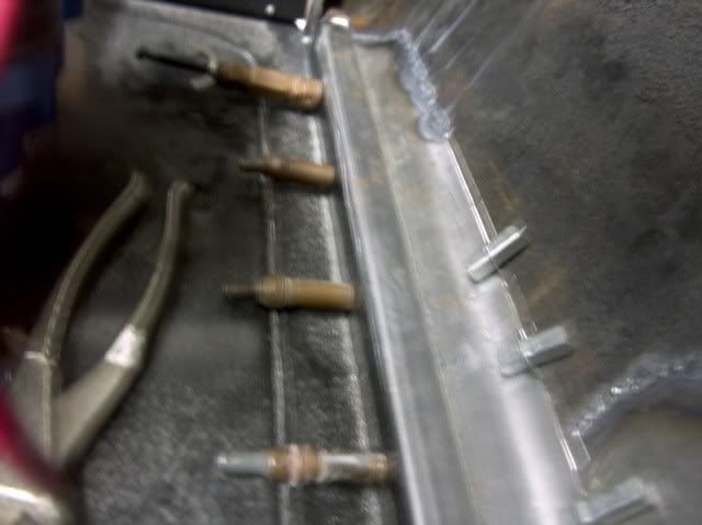
Got the repaired piece all cleaned up in the sandblaster, and the car prepped for it to go in.
Here's the plug weld holes drilled, ready for the welder to be fired up:


There we go.....that should hold paint for awhile
-
02-10-2012 08:56 AM #6
CHR Member
- Join Date
- Jun 2008
- Location
- Leonardtown
- Car Year, Make, Model: Walking
- Posts
- 1,228
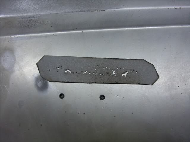
Here's an area with a bit of bondo in it, always worth further investigation. Once removed, it showed the damage. This is a 1965 vintage, so probably lucky there isn't more to deal with than this. Someone's version of a previous repair involves banging in the rust holes and covering up the mess with body filler. We'll try to do one step better than that, install new metal.
Here's the point of no return, hope I can bend up a replacement!
Started off with a piece of steel, laid out the rough size and bend lines, then trimmed up a bit.....

Made a new radius die to match the bottom bend on the original piece....
Made some bends along both sides, not too much at first. Need to get in there with the Lancaster shrinker, which won't tolerate too much of a crease in the corner.

Keep progressing along, bend a bit more, shrink some more, etc...


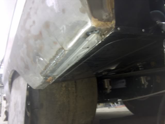
Once you have the basic shape, then use the shrinker along the wheel opening flange on front to get the same contour as the original. Then I used the large radius die again to add this same contour across the whole patch panel by giving a slight bend (real slight), moving about a quarter inch, repeat, etc.... The radius in the corner was trimmed slightly different from stock to provide a bit more room for the rear tires. The other side will be trimmed to match.
Installing the patch panel


Much better!
-
02-10-2012 09:24 AM #7
CHR Member
- Join Date
- Jun 2008
- Location
- Leonardtown
- Car Year, Make, Model: Walking
- Posts
- 1,228
For some reason, drip rails don't tend to like me. This is the second car in a row needing drip rail repairs.

Using the cut-off wheel to grind/remove the spot welds.

Dominoes, anyone?
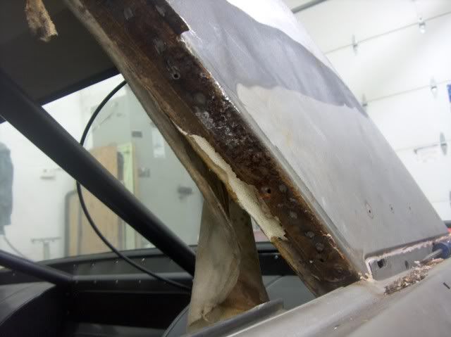
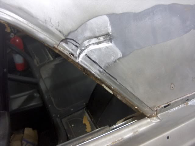
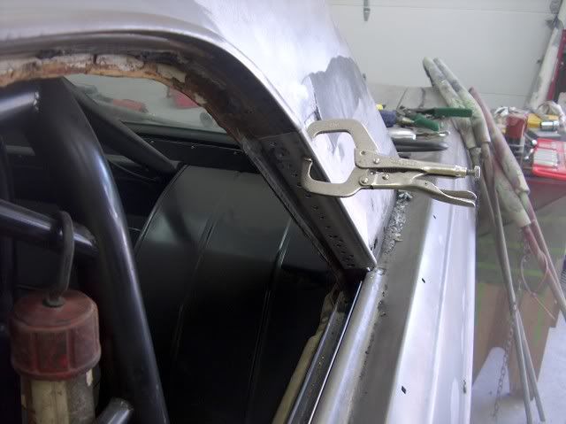
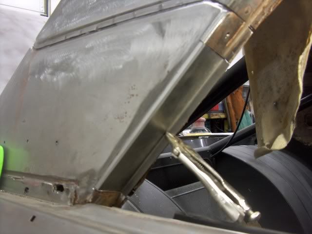
Looking at the rust just above the drip rail, it looks like it is up into the roof panel as well.
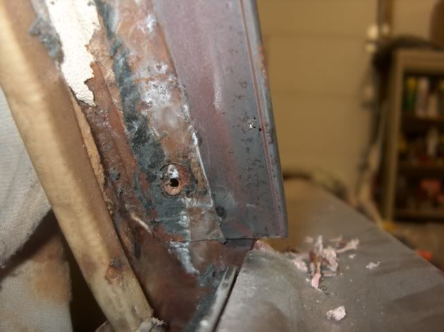
The first order of business will be to remove the leaded seam to expose the lapped joint between the two panels. A soft flame on the acetylene torch and a wire brush makes short work of it.
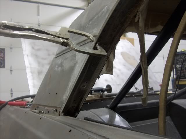
The closer I stay to the crease of the leading edge of the sail panel, the less the metal should move. A quick check of the back side shows that, although it will be tight, I can get a dolly in there. The top piece is marked a bit larger, to give room for welding and grinding the seam for the repair panel below it.
An ice pick and a bit of grinding will show the extent of the damage, and let us know how far up we need to go for good metal. I did have to trim the top opening a bit more.
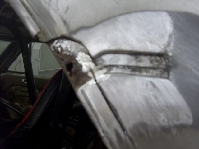
....and before we get too carried away with the cut off wheel, let's mark some reference lines so the new piece will go back in the same spot.
Opening up the tin can....also will need to grind away the spot welds holding it to the inner sail panel.
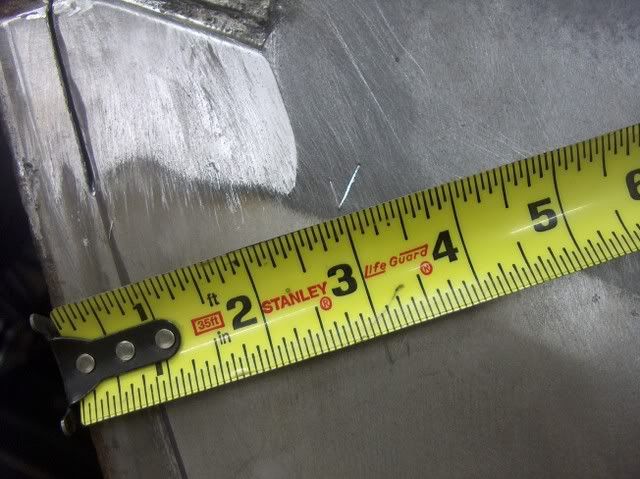
In bending up the new piece, there needs to be a joggle just above the drip rail.
The machine you see in the background here is actually what I should be using, but I think it would take longer to make the dies than what I have in shop time this evening.
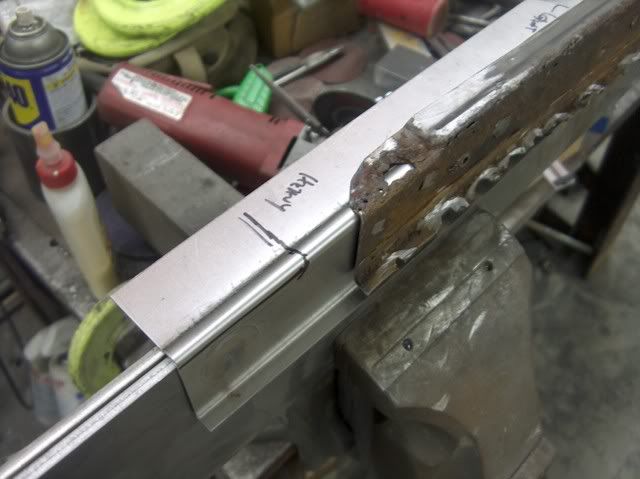
So we'll cheat, especially since I found a flat bar in the scrap pile just the right width.....

Some hammer work on the welding table will reform the end, and then we can trim and test fit this piece. Still need to trim a bit more to match my reference marks, but it's real close. And as it's late, we'll have to put off welding until tomorrow.
-
02-10-2012 09:43 AM #8
CHR Member
- Join Date
- Oct 2007
- Location
- Petaluma
- Car Year, Make, Model: 48 Ford F1
- Posts
- 9,795
Nice detailed photos of the metal works, Thanks for sharing. I think your work looks excellent."  "No matter where you go, there you are!" Steve.
-
02-10-2012 09:56 AM #9
CHR Member
- Join Date
- Feb 2007
- Location
- Santa Monica
- Car Year, Make, Model: 37 Ford tudor humpback
- Posts
- 1,988
Wow!!! Awesome metal work!!! I'm a total novice but totally fascinated by it!"It is not much good thinking of a thing unless you think it out." - H.G. Wells
-
02-10-2012 10:23 AM #10
CHR Member
- Join Date
- Jun 2008
- Location
- Leonardtown
- Car Year, Make, Model: Walking
- Posts
- 1,228
Thanks for the comments guys!
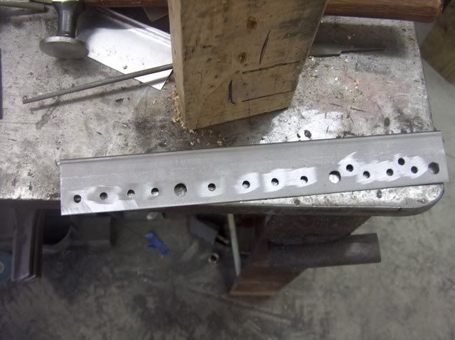
Here's the final drip rail, complete with 3 clearance holes for the window weatherstrip screws and various plug welds.

Oops, still need to finish the roof patch!

Test fit and installation of the drip rail:
And there you have it.
-
02-10-2012 10:25 AM #11
CHR Member
- Join Date
- Jun 2008
- Location
- Leonardtown
- Car Year, Make, Model: Walking
- Posts
- 1,228
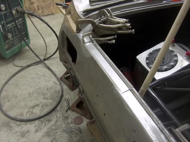
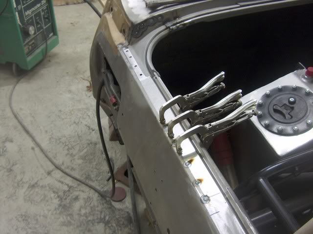
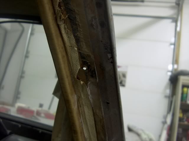
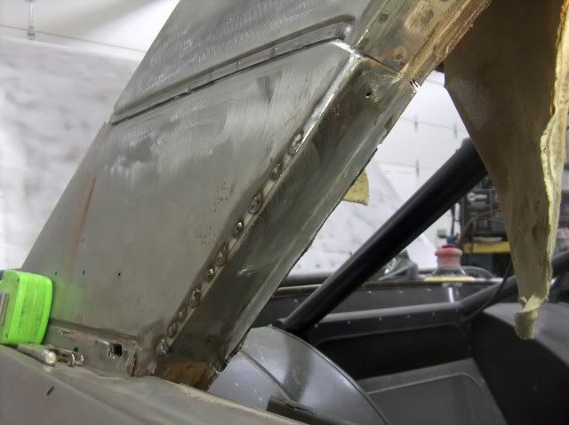
After fixing the drip rail on the drivers side, the other side is already suspect for similar damage. The owner was hoping we could get by with leaving the passenger side alone. There was some deep pitting in the drip rail, and some visible where the seam sealer was removed. Found two small holes in the outer part of the drip rail, which I thought could be welded up if I had to........but where the inner part of the drip rail spot welds to the underside of the sail panel, I could feel the telltale signs. The metal had swelled up, giving the indication of some rust scale lurking between.
Note pin holes:
The owner really didn't want to cut this side open, so what's an anal-retentive guy with a bunch of raw sheet metal to do? So I waited for him to go on travel for work, called him up and then told him the bad news.

Replacement fitted and welded:

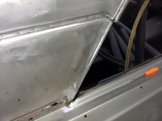


There, all put back together, before he could protest too loudly
-
02-10-2012 10:29 AM #12
CHR Member
- Join Date
- Jun 2008
- Location
- Leonardtown
- Car Year, Make, Model: Walking
- Posts
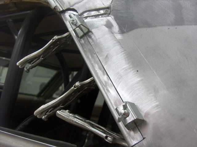
- 1,228
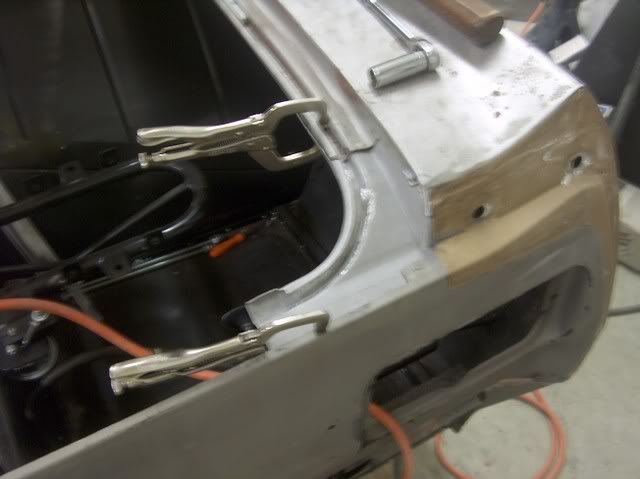
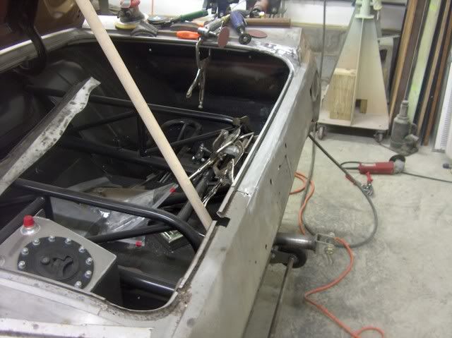
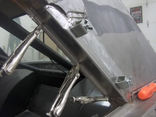
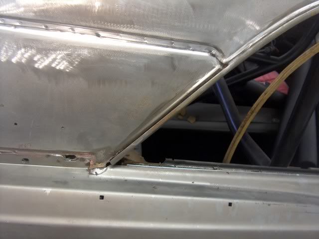
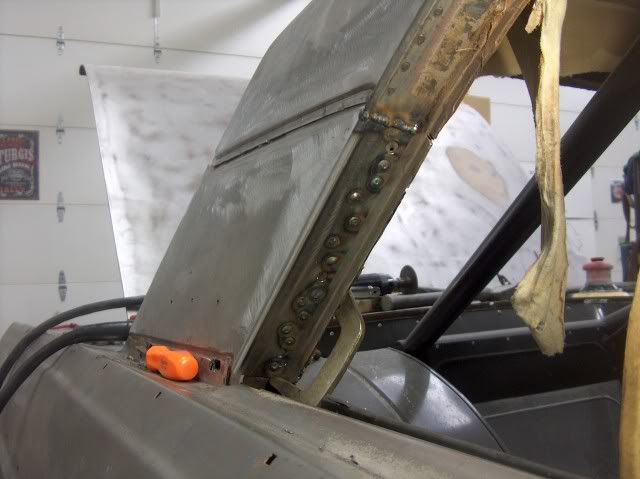
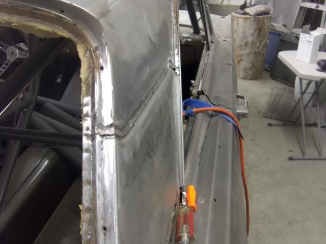
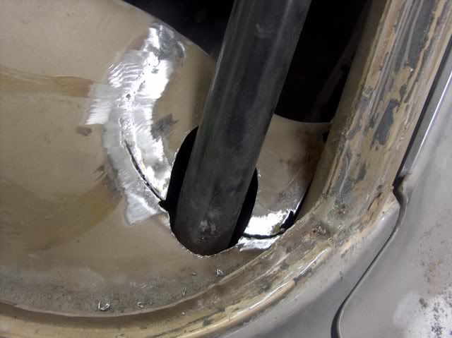
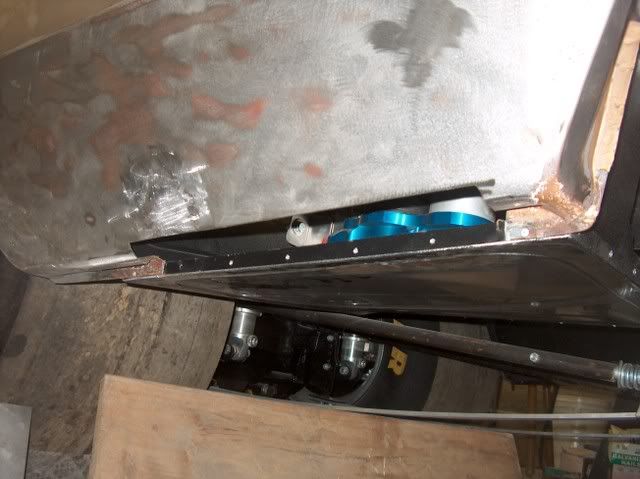
Working on getting the hood pins installed...... The goal was to finish up the body fitments and get the fenders, doors, hood and trunk lid all removed so their insides could be painted. The frame guy, Chris in Fredericksburg, had cut out the corners of the dash when installing the roll cage, and I trimmed the holes around the tubing a bit better, and finished welding where he couldn't get to when the windshield was still installed. The dash holes for the cage tubing will get some trim-lok edging to finish off the hole.

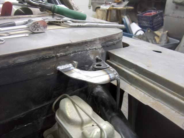
The owner had shown up about the time I finished the dash, and we got to work on the hood pins. I didn't want to just have an angle bracket screwed to the firewall, so I came up with these brackets out of 12 ga, they turned out nice and rigid! The front hood pins used the original holes in the core support that were for the hood pads.
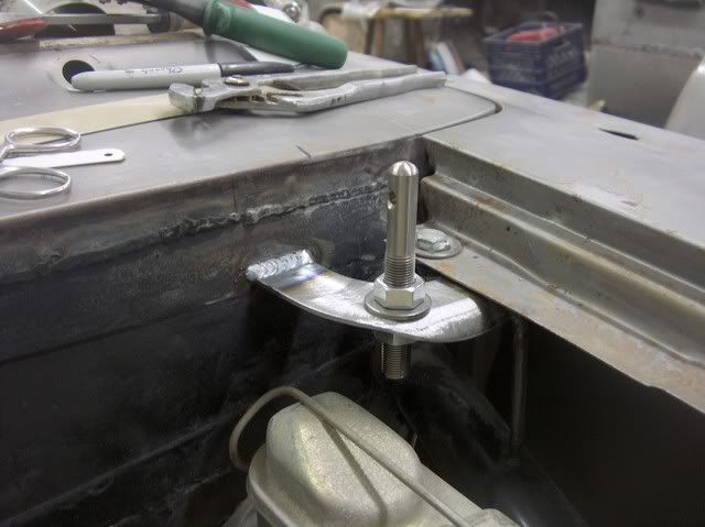
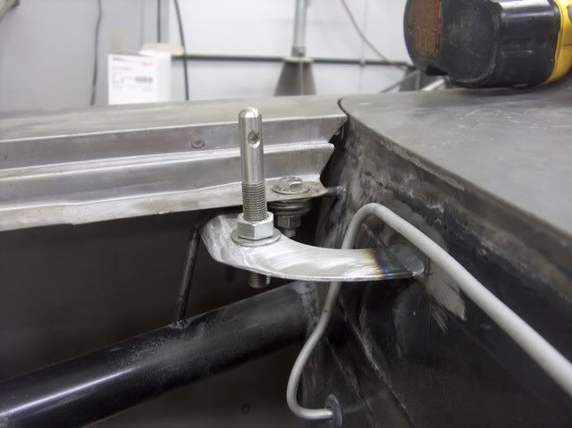
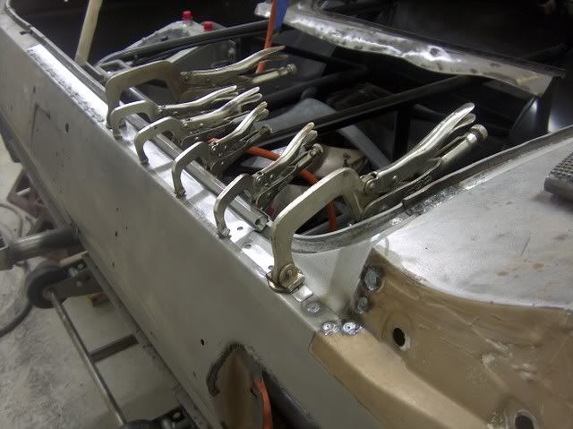
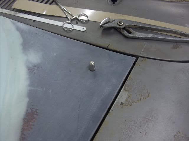
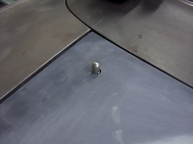
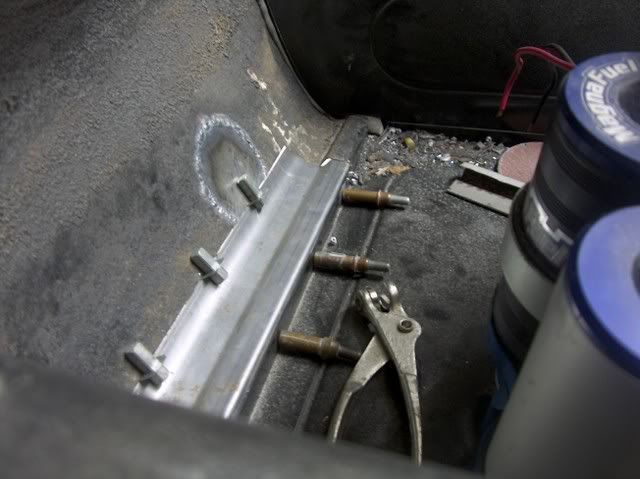
Hood drilled. Took some 7/16 bolts, ground a point and bolted in the hood pin holes to use as "spotters" for locating the holes in the hood.
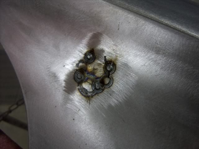
Now to concentrate on fixing 6 remaining pin holes :fingerscrossed:
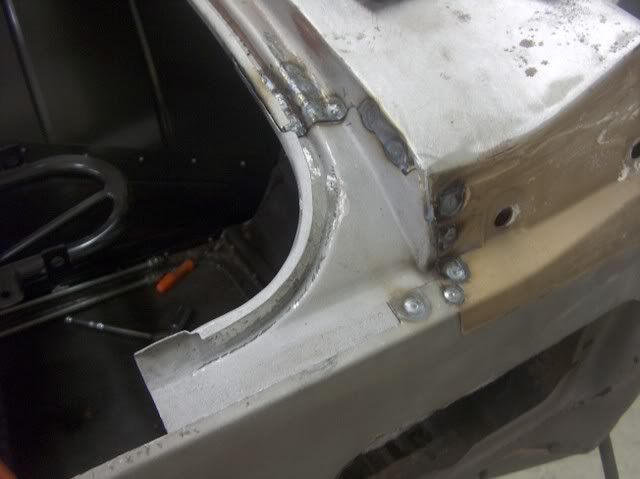
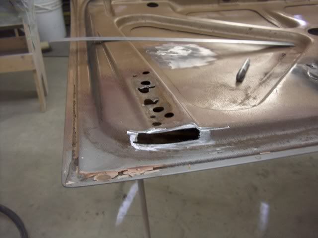
Three above the wheel opening were easily filled with the mig, but the next three were about midway back on the rear quarter and about two inches up. Don't know where these came from, unless some bright individual had a rag stuffed down there to collect all the leaking rain water. All attempts to weld these holes just opened the holes much bigger, so i decided to cut a circle around the three and replace with some new metal.
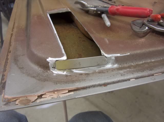
Now I'm not sure about what happened next, whether it was the domino effect, or just plain my luck. But when finishing off the welds of my patch, I noticed some of the telltale dark brown spots on the bottom side of the quarter. These are a tell tale sign of pitting working it's way through from the back side. Ice pick easily went thru, so I took the crud thug to the entire lower quarter on the inside to reveal the rest of them. Quite a bit of pin holes and deep pitting, so another hole was cut. The crud thug was used on the passenger side also, but it did not need any repairs. Whew!
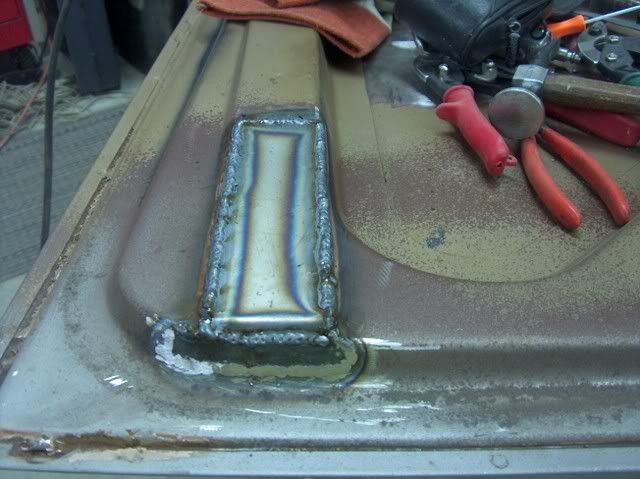
In this repair I clamped everything up, started the weld from the back end, and just removed clamps as I went. This allowed the gap to close up for a nice tight fit for butt welding.

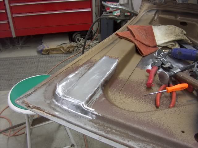
Inside view:

-
02-10-2012 10:33 AM #13
CHR Member
- Join Date
- Jun 2008
- Location
- Leonardtown
- Car Year, Make, Model: Walking
- Posts
- 1,228
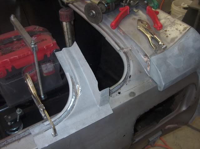
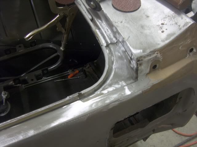
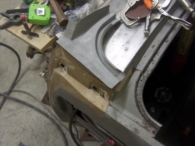
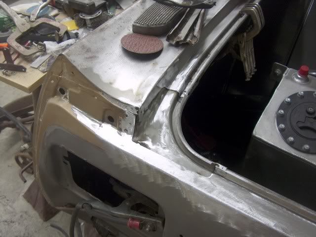
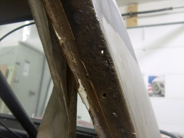
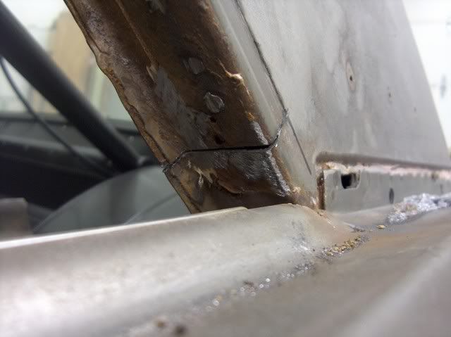
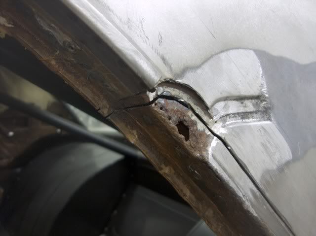
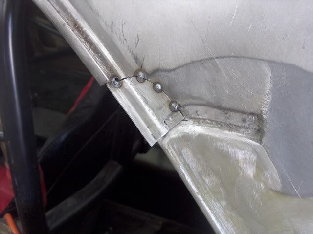
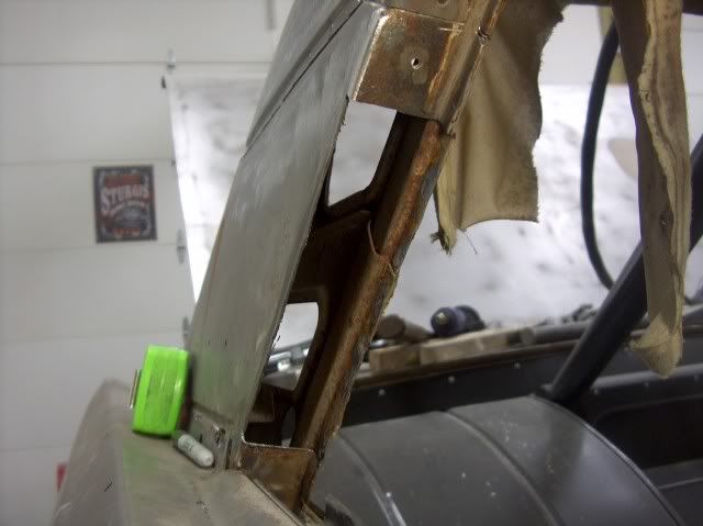
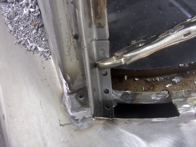
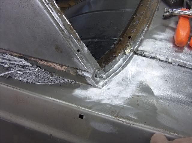
Noticed this was lurking while cleaning up the rear window channel, hoping to get a step closer to primer.
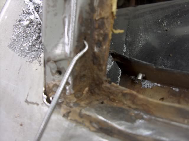
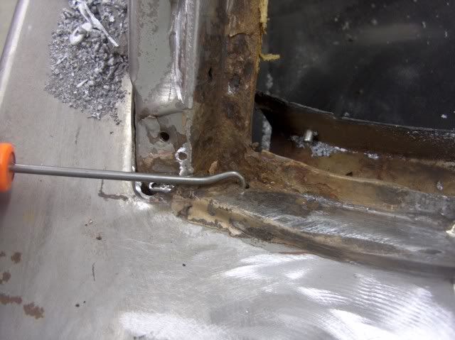

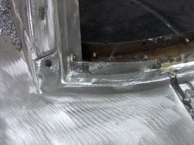
The first step I normally take is to use the pick to check the surrounding area for any hidden damage, and decide how far to take the opening. Once you find solid metal, the next consideration is the ease of dressing out the repair. It's easier to grind and sand on an outside radius than an inside one, so that is factored into the cut size. Sometimes you don't have a choice, but best to make it easier on yourself when you can!
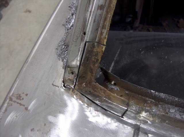
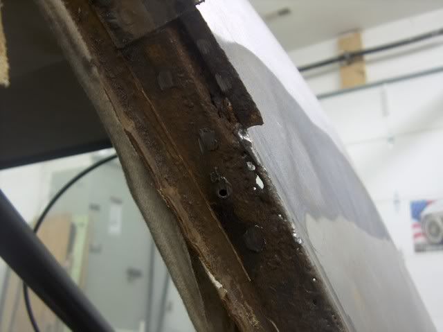
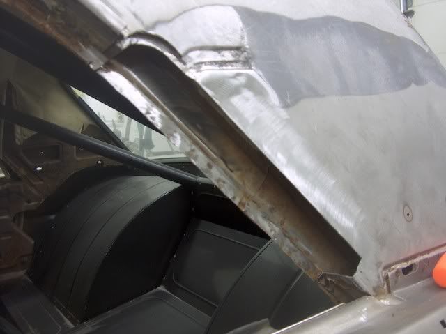
The channel is actually made in two pieces. The spot welds in the pinch weld area are removed from the top layer to remove the damaged pieces. The vertical piece actually travels down beyond the bottom of the window in this case, so that will be installed first. A new piece is cut out and bent to fit, and final sanding/grinding to get a tight weld joint.
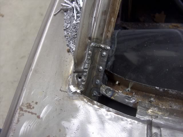
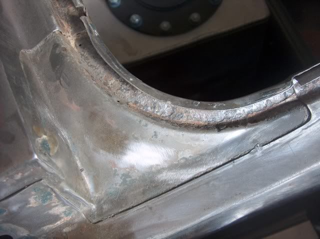
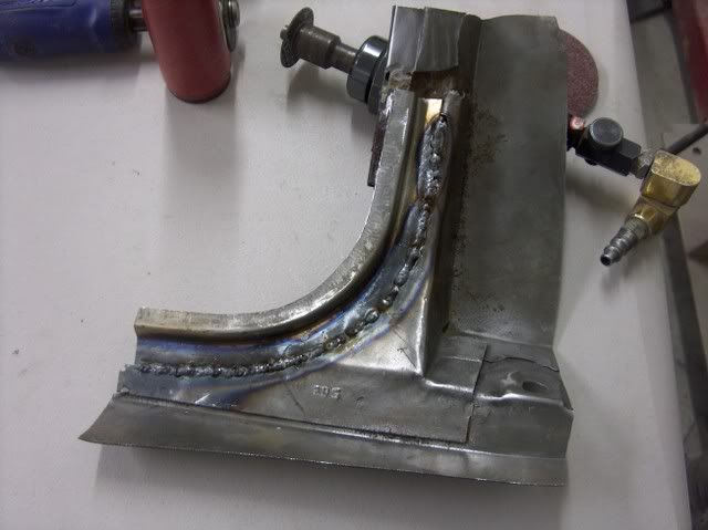
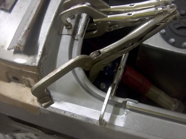
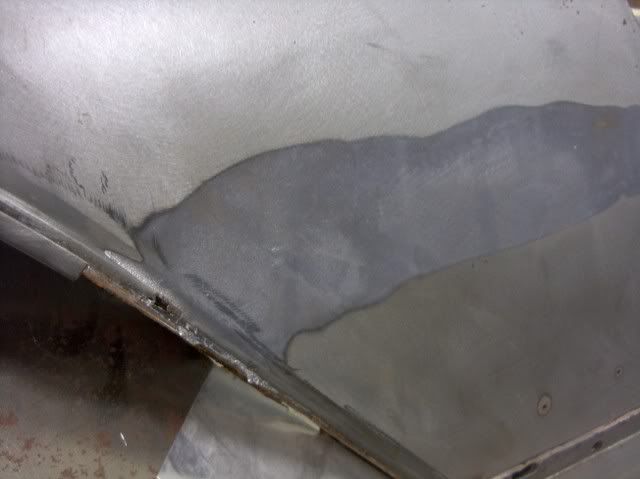
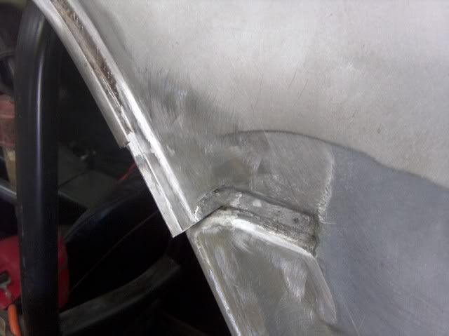
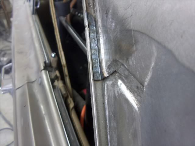
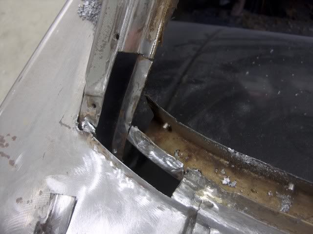
The bottom piece has a radius in two directions, slopes up and in.
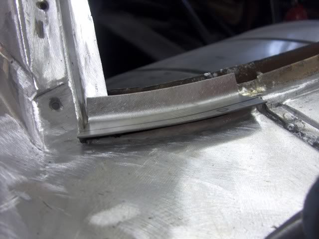
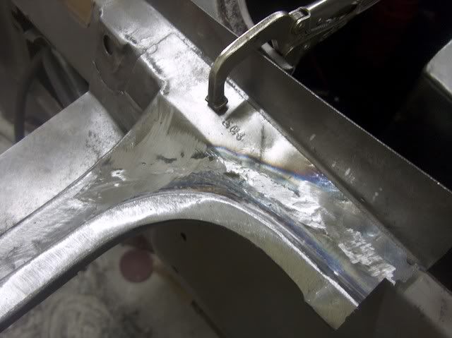
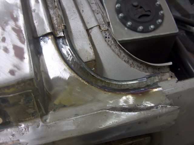
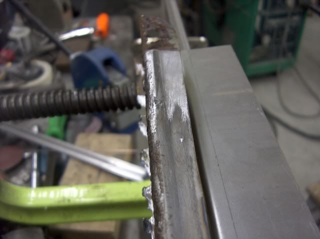
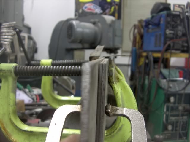
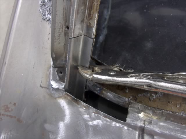
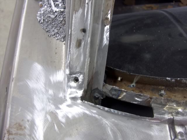
The outer (rear) radius was hammer formed after the shrinking and stretching was done. Then trimmed to fit and welded in place.
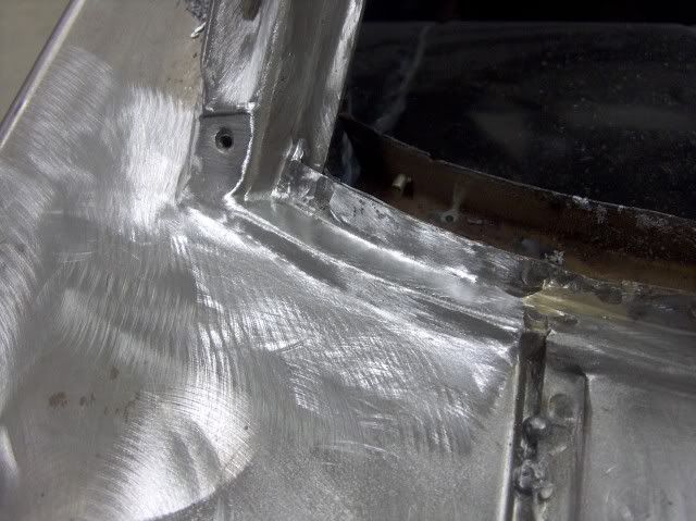
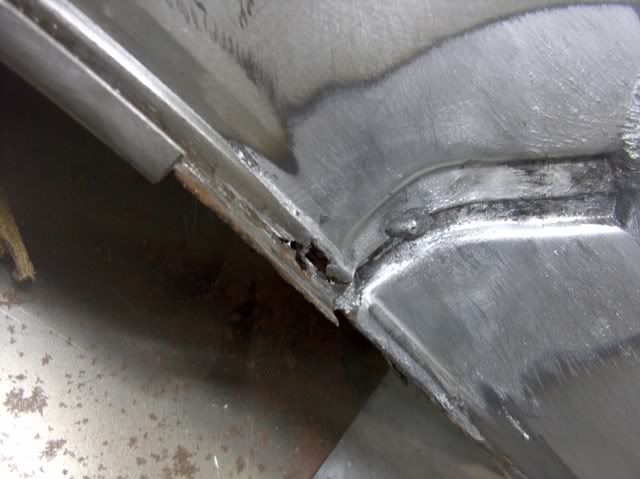
The inside corner joint was welded and cleaned up with a ball nose burr grinder, to keep water traps to a minimum.
-
02-10-2012 10:44 AM #14
CHR Member
- Join Date
- Jun 2008
- Location
- Leonardtown
- Car Year, Make, Model: Walking
- Posts
- 1,228
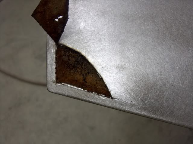
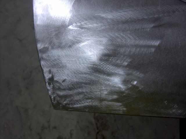
We did run across more metalwork to fix prior to painting. The front fender had a hole for the antenna, which he didn't plan to use, so it was filled.
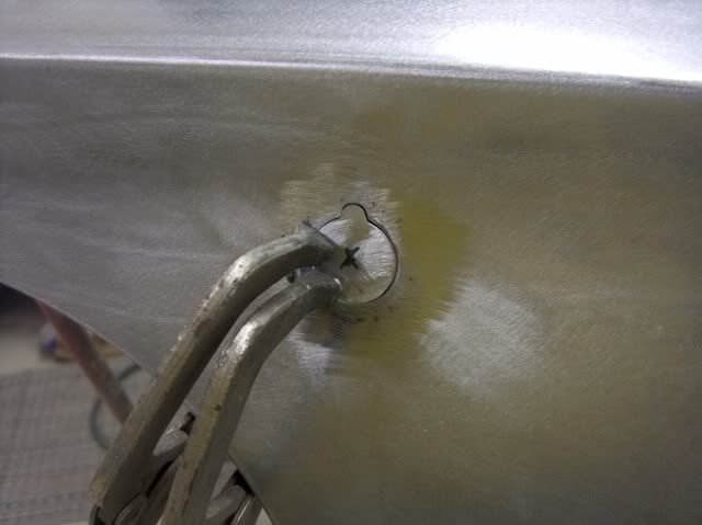
The trunk lid hinges had been relocated inboard to clear the rear tubs, so the original holes were removed and filled.
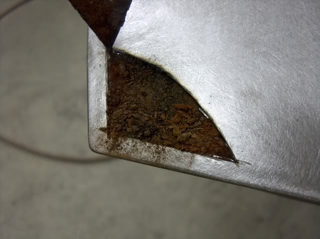
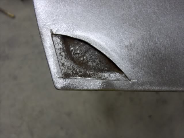
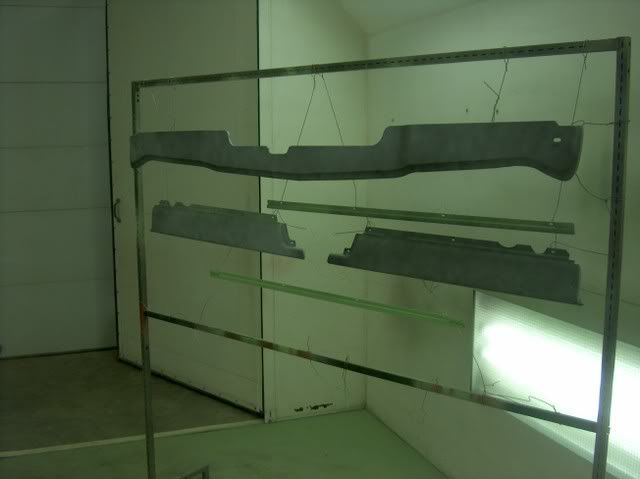
And just when you're ready to load parts in the paint booth, this shows up:
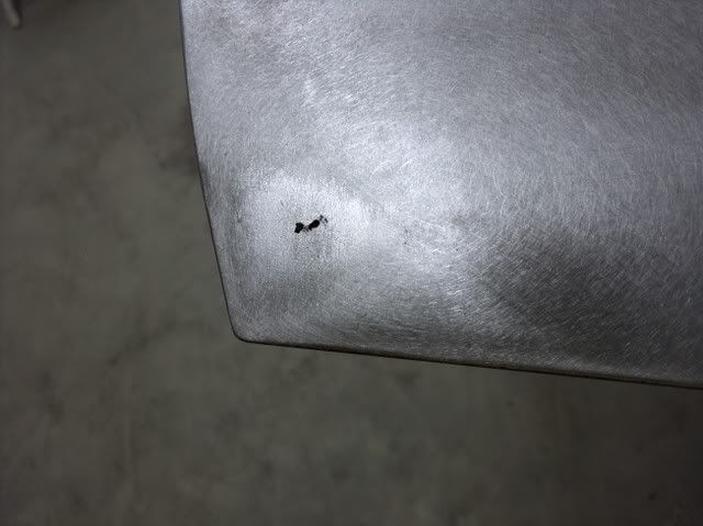
Wonder what caused that?
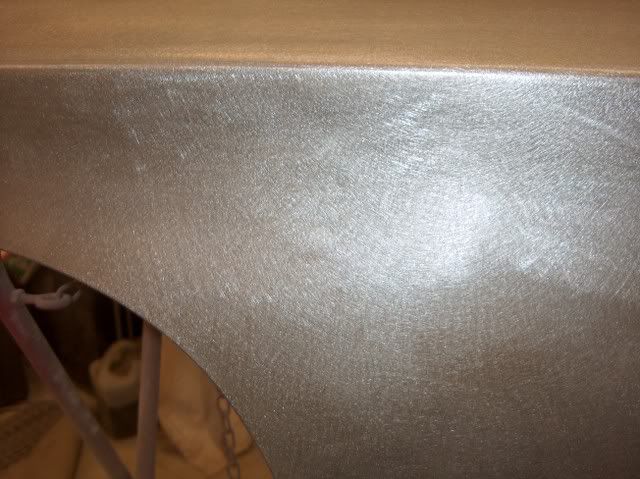
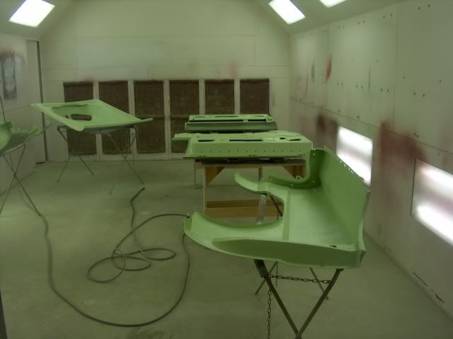
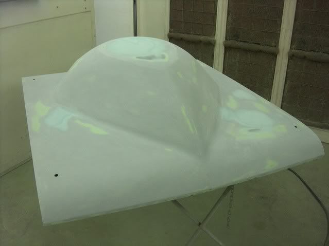
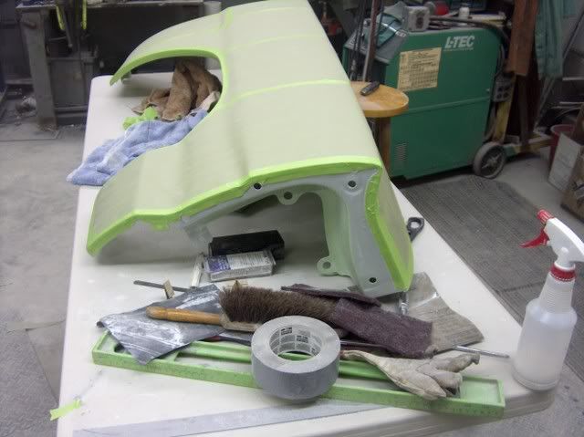
Back sides primed (H/K KP-2):
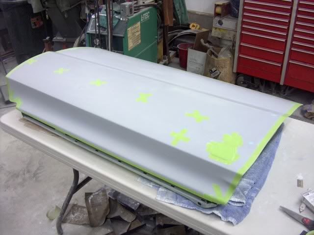
Front side primed, slick Sand high build, and guide coat (next day):
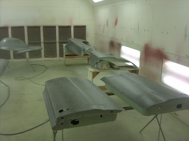
Hood all one color, it's starting to grow on me.
-
02-10-2012 10:51 AM #15
CHR Member
- Join Date
- Jun 2008
- Location
- Leonardtown
- Car Year, Make, Model: Walking
- Posts
- 1,228
A slight bit more progress, got the hood and trunk lid blocked out and low spots addressed. Will need a couple more coats of high build later this week as well as some of the few remaining bare parts. The doors and fenders look like they will get by with wetsanding only.
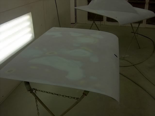

I did have some help with sanding.
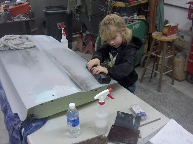
One front fender left to sand, and then I'll spray another couple coats on the hood and trunk lid.
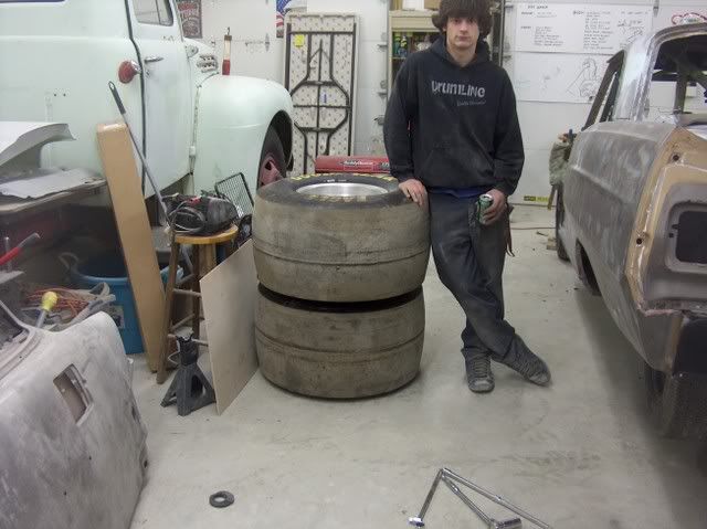
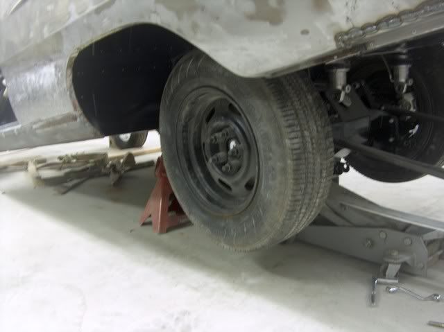
My nephew Chris did some prep work while I continued wet sanding, the rear tires were removed so we can trim a bit more inside the bottom edges of the wheel opening. We had a set of "painting grade" wheels and tires, but had to open up the bolt holes to accomodate the 5/8" studs. Also had to unbolt the bottom of the coilover shocks to get the rear tires off. Forgot how large those beasts were
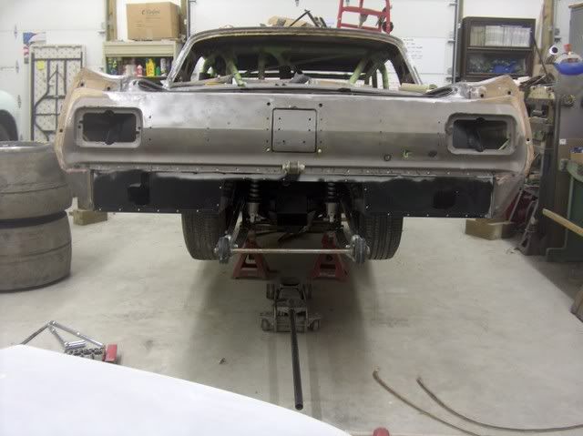

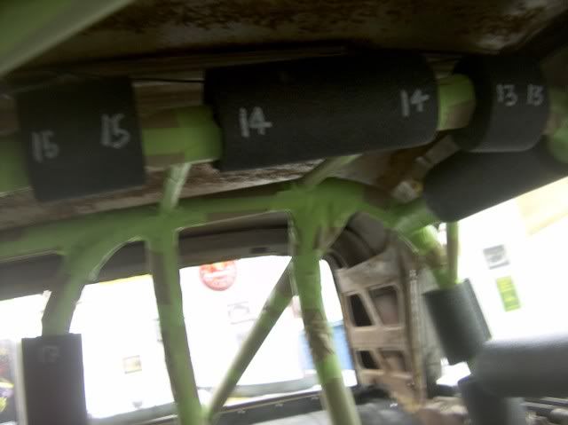
The roll cage and chassis has been IHRA/NHRA inspected (to 7.50 I believe...), and we don't want any more paint on it that would interfere with weld inspections, so Chris masked off all the roll cage, and then he and Brad (the owner) cut and fit the padding to get it ready for the upholsterer. Here's the official "treasure map" to locate all the pieces.


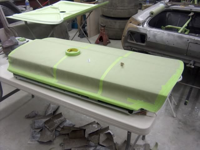
I had sprayed another couple coats of slick sand yesterday on the trunk lid as I still wasn't happy with it, and it turned out pretty nice this time. Started masking off the holes and front sides of the body panels, getting ready to spray some red on the back sides.
 Reply With Quote

Tags for this Thread
Posting Permissions
- You may not post new threads
- You may not post replies
- You may not post attachments
- You may not edit your posts

i've enjoyed the years here . made a lot of friends. most who have left. i see no reason to continue with this so hope to see you somewhere else. i dont think this site will ever be back. it's lived...
Dead!