-
11-30-2016 09:23 AM #1
Fab of bottom door panels for 1937 Buick
I'm finally ready to tackle the rust repair on the bottom of the doors of my 1937 Buick. Like most panels, there are no aftermarket parts, so I need to fabricate. The shape has a .875" radius near the bottom that leads into a sharp corner and vertical tab (return). The part is further complicated by the gradual curve of the door from front to back. I will need two sections that are 38" long and two that are 21" long.
Does anyone have suggestions for equipment, or process, to fabricate this shape?
Thanks
-
Advertising

- Google Adsense
- REGISTERED USERS DO NOT SEE THIS AD
-
11-30-2016 09:47 AM #2
Half deflated GK slick on an English wheel:
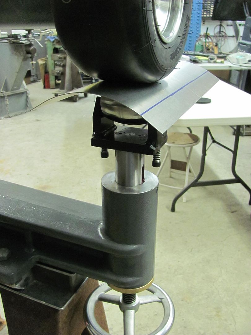
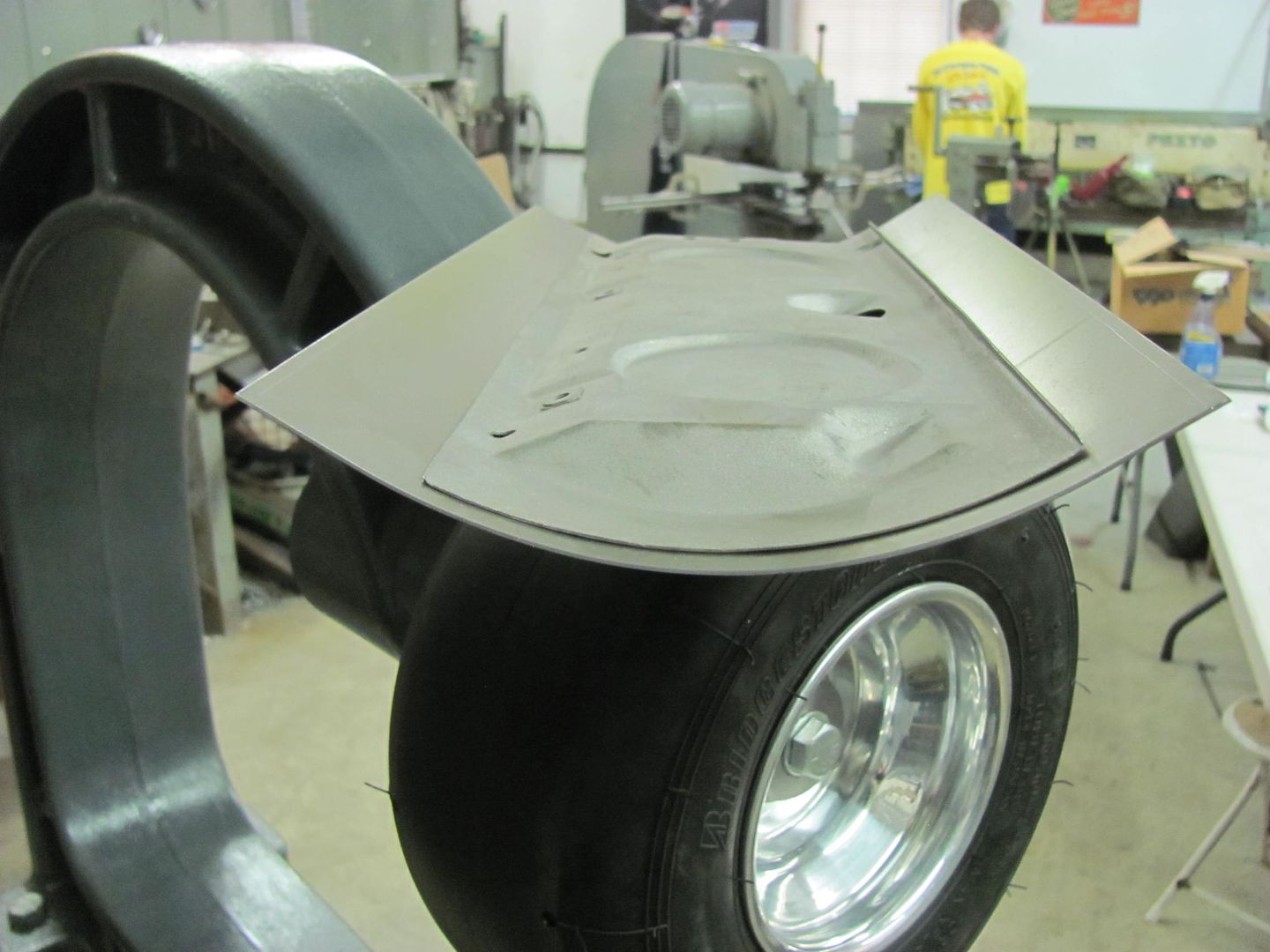
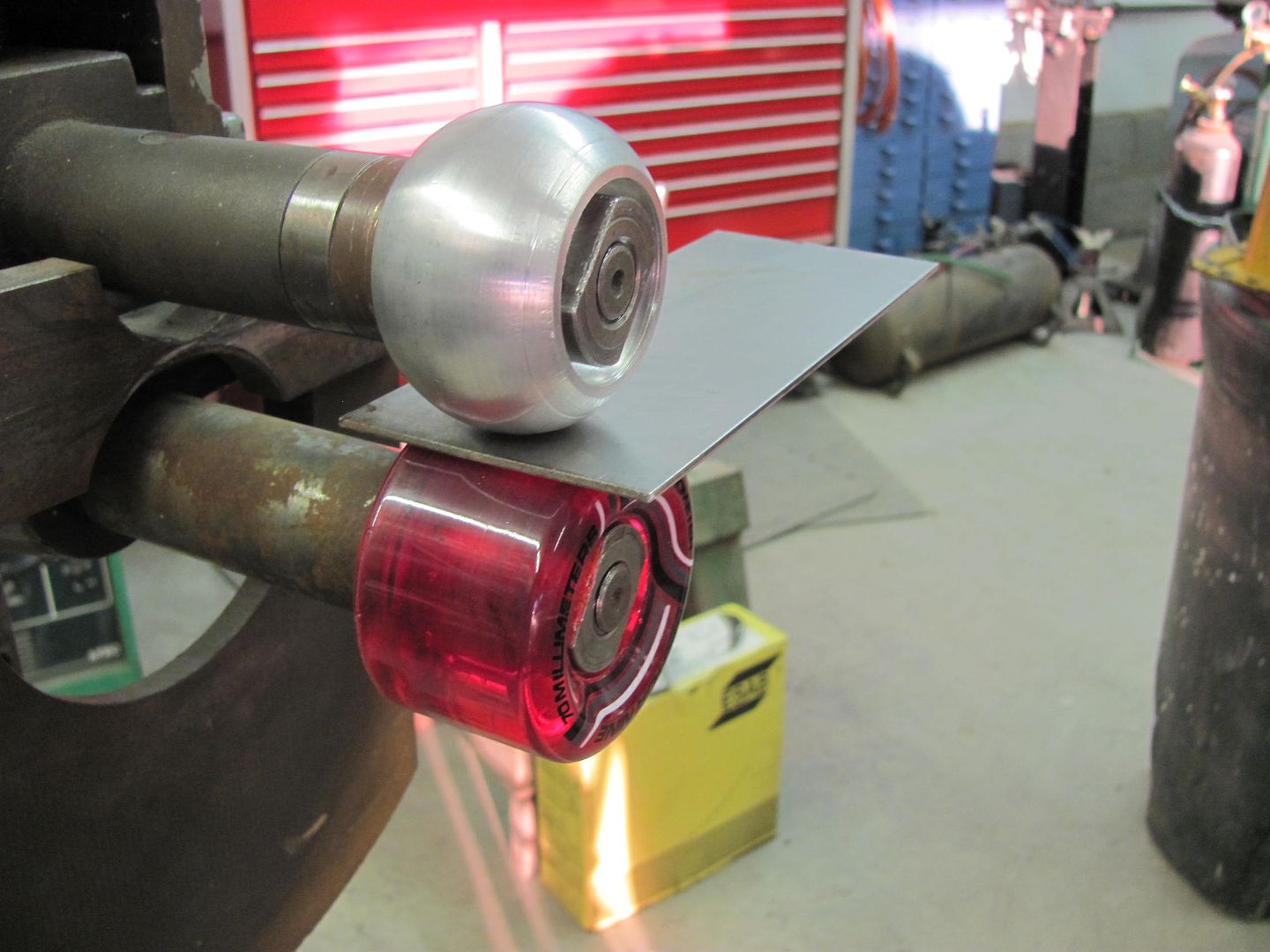
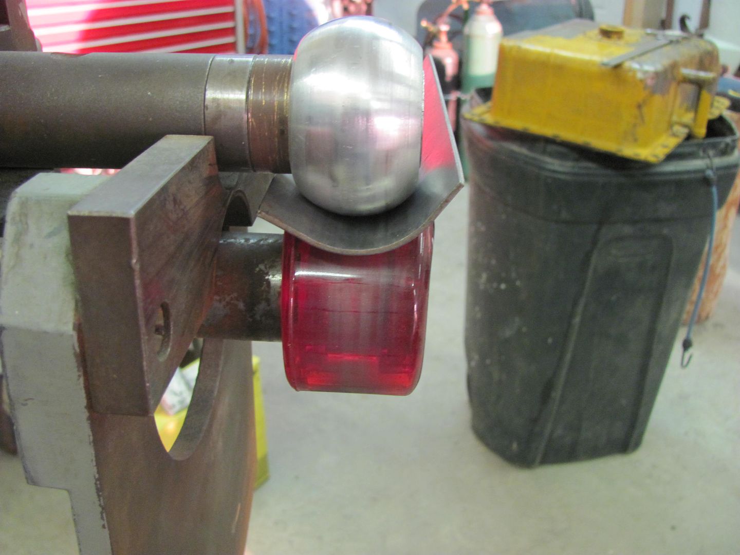
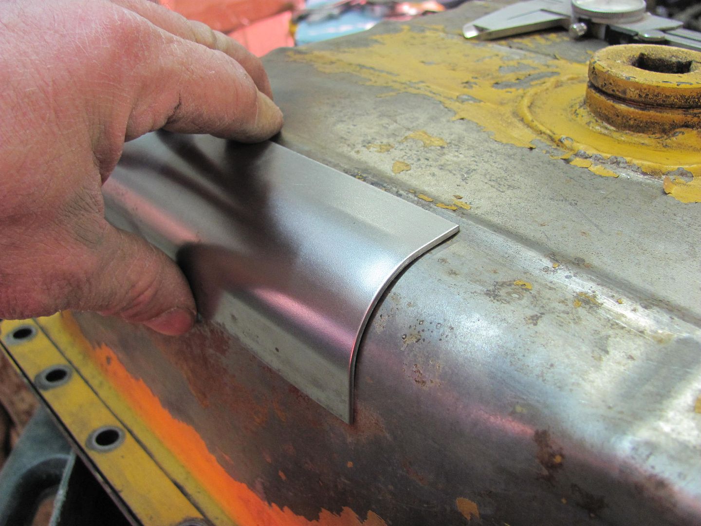
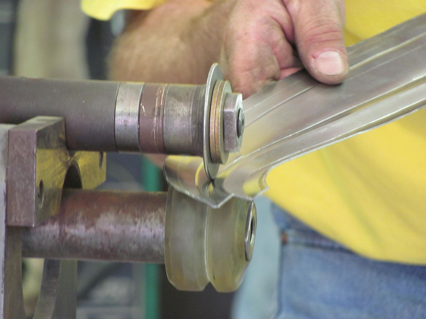
Or on a smaller scale for tighter radius, rounded upper die into a skateboard wheel on the bead roller... as seen in this D5 oil pan repair...
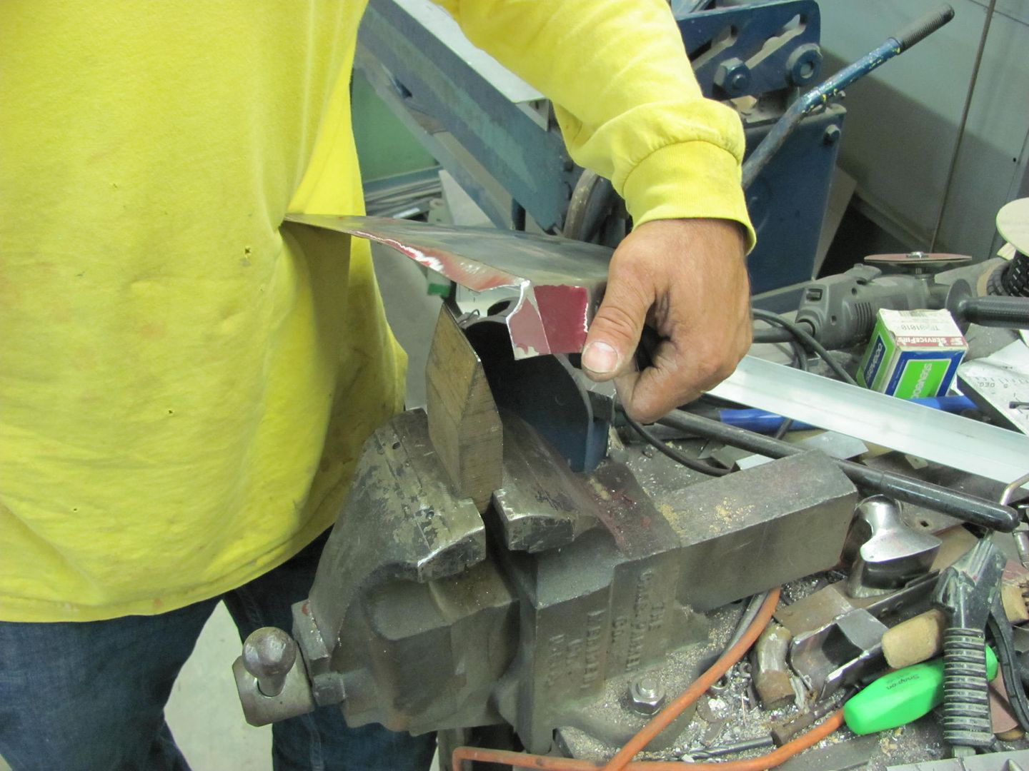
The lower crease into a vertical flange can be done on a tipping wheel/die or manually by a number of methods...
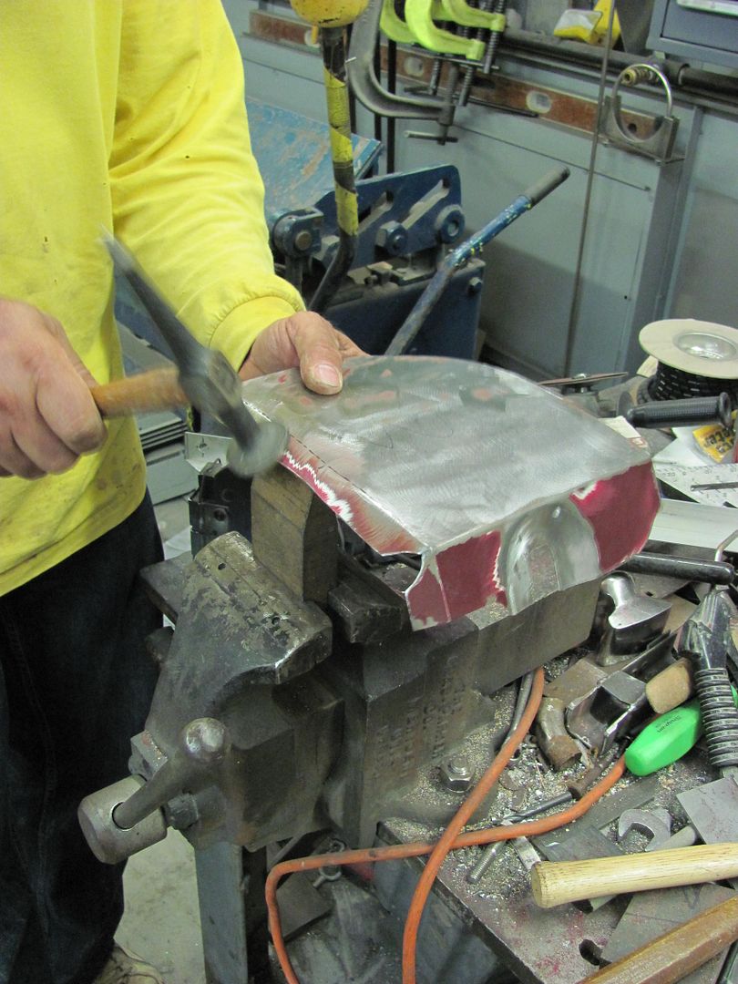
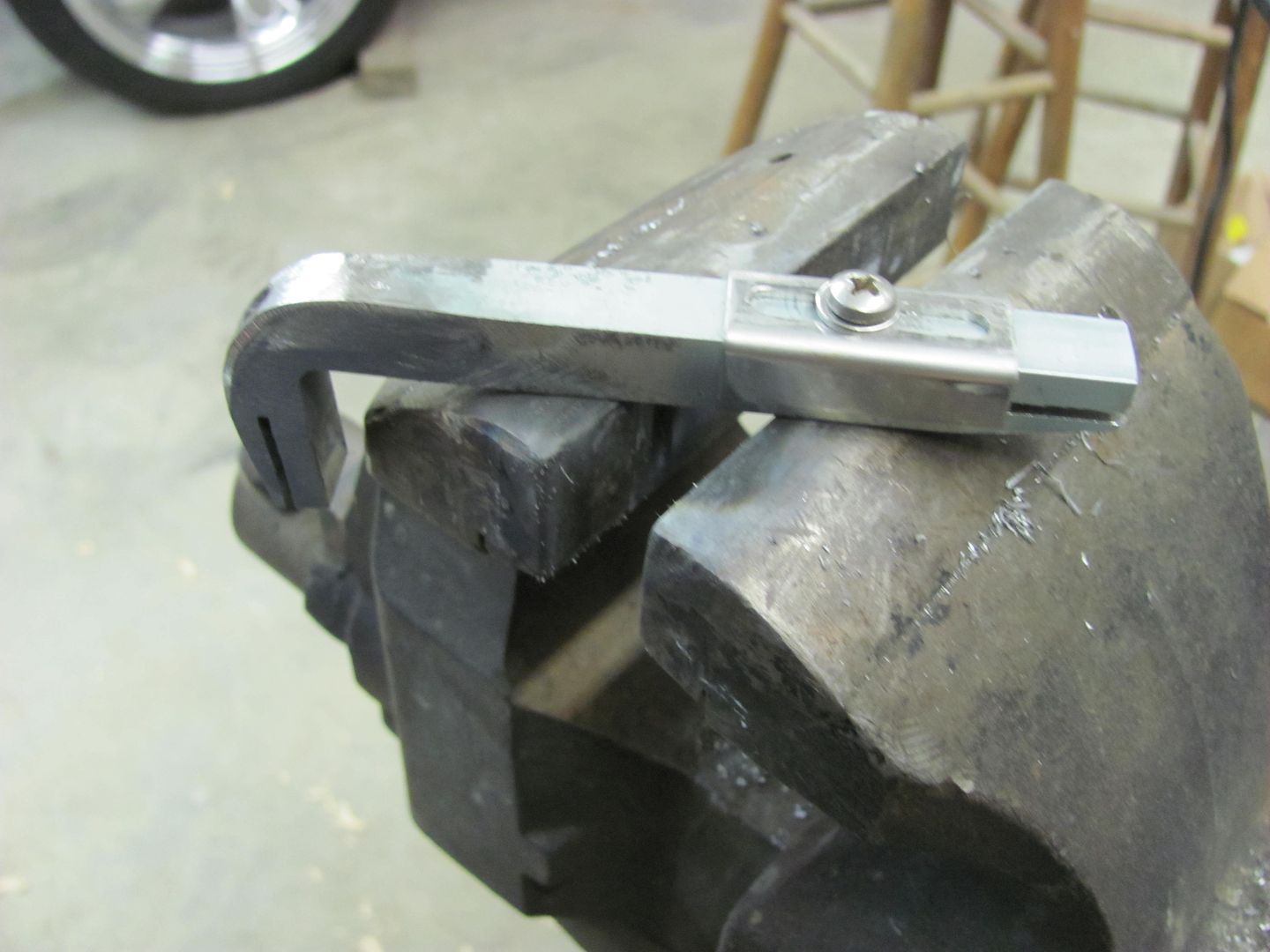
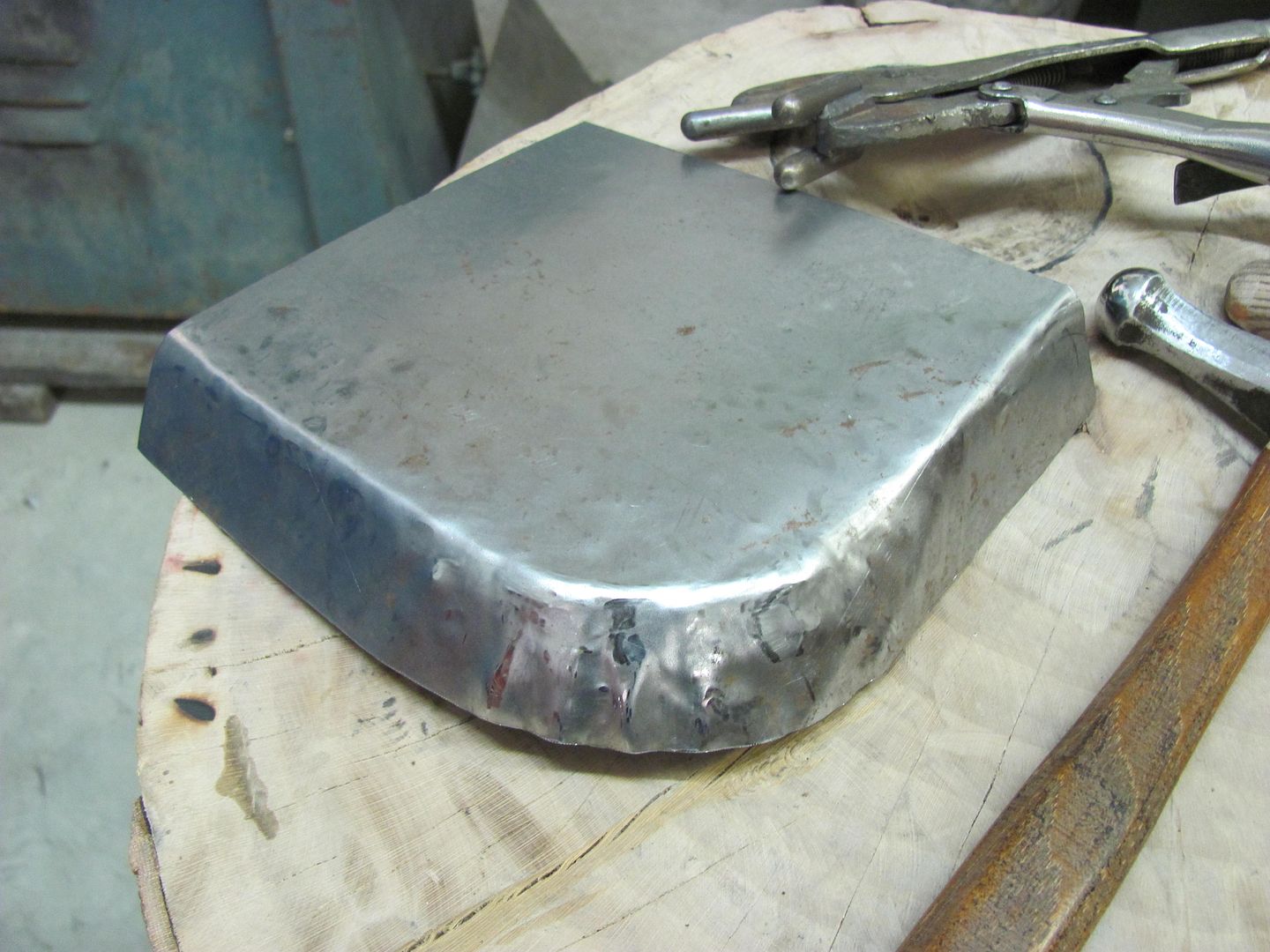
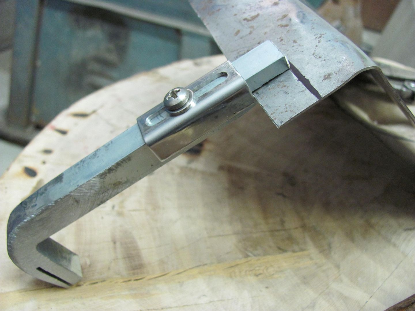
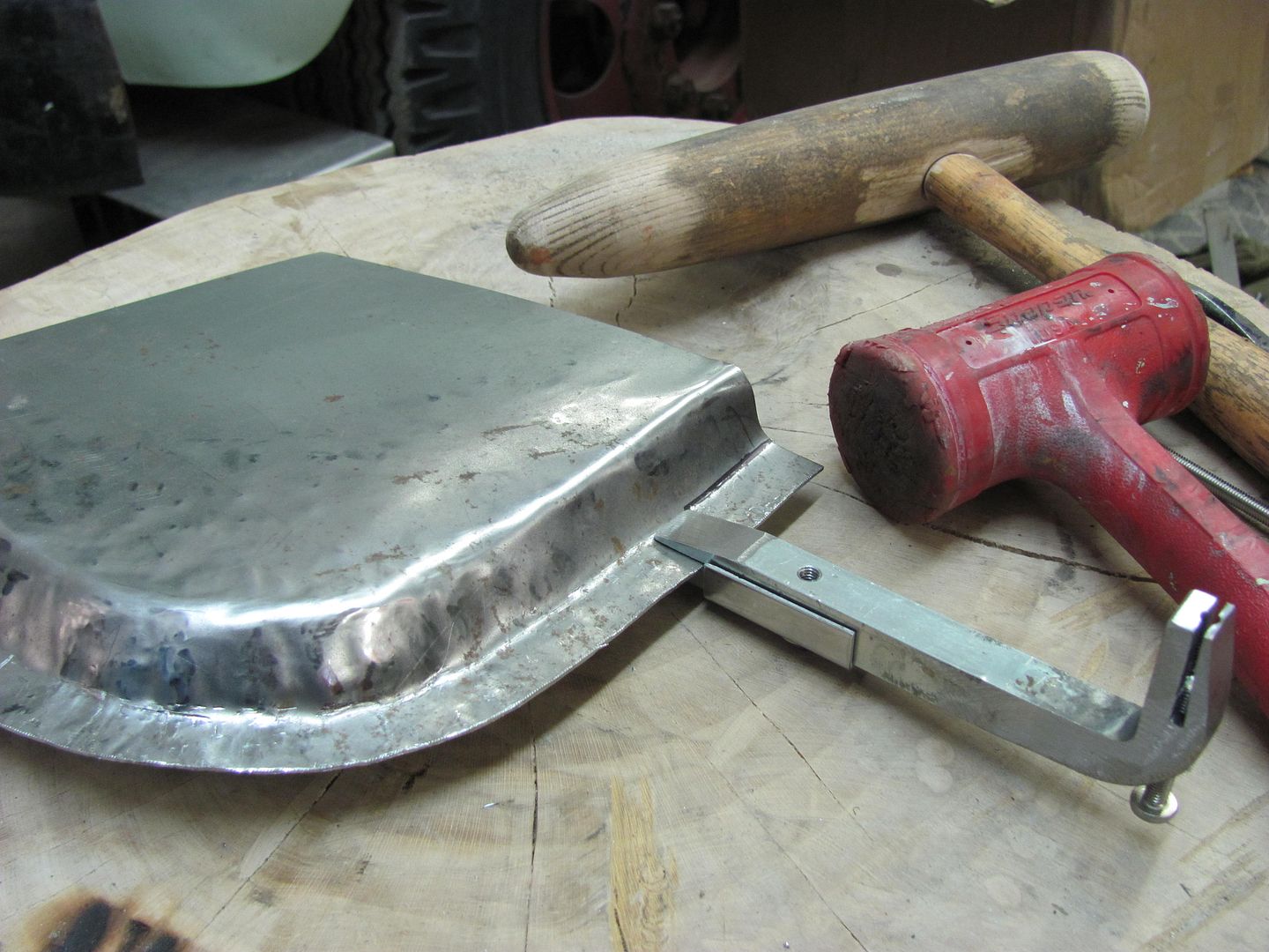
The gradual shape can be added by using an English wheel as a fulcrum/anvil approach, keeping a gap between the wheels and adjusting fulcrum pressure applied as neededRobert
-
11-30-2016 10:04 AM #3
Thanks for these great pictures. Sounds like a bead roller needs to be on my Christmas list. Can also use it to make floor boards.
1) Is this the order would you recommend for the steps be taken?
- make .875 radius
- make large curve to match curve of door front to back
- make crease into vertical tab
-
11-30-2016 10:11 AM #4
Do you have any better pictures of the outside of the door that show the entire thing?Robert
-
11-30-2016 10:26 AM #5
Here is the outside of that door.
I probably need to replace the lower 6" to 8 " of the outer skin.
The curve from front to back is very gradual.
I will be fabricating steel inner structure from tubes and angles to replace the wood that was removed.
-
11-30-2016 12:25 PM #6
To better decide where to put a seam for the door skin, one would need to see the entire door and all the components/features. Is there a removable panel or opening inside the door to facilitate access for planishing your weld seam? That is normally my first priority, as any weld seam across the bottom of your door is going to cause weld distortion. The second consideration would be panel features that help to control the distortion. As you travel up from the (.875) radius at the bottom, the door panel appears to get very flat very quickly. These flat areas are recipes for disaster, as they are more prone to movement and distortion from the weld process. If you need to come up 6-8" due to rust in that area, know that a flat area like that is not an ideal location for the seam, especially if you have no access for planishing. If the area at the bottom is still solid and you can make the seam closer to the radius, this may help, but you still need access for planishing. Perhaps you could cut an access hole if one does not exist that could be re-welded in after planishing the outside skin.
If the body lines and door features are such that the only access for planishing is up higher, and only beltline "bead" feature that would help to limit weld distortion is up higher, I would lean toward making a new door skin and putting the seam along a beltline bead. You would more than make up for the extra fabrication time in minimizing weld cleanup and planishing efforts, and would have a better job in the end.
Weld process... if you plan on doing this with a MIG welder, you will definitely need planishing access. I would recommend to use TIG in a non-stop weld from one end to the other, after tacking the panels together to prevent movement.. A tight, gap free joint is VERY beneficial with this process. As shown in this video, Tacking:
https://www.youtube.com/watch?v=aTqQJoecqCw
After the panels are tacked, welding from one side to the other in as long a pass as you can will further limit distortion from welding as the panel is heating up progressively as you travel across the panel and cooling in the same fashion. With a MIG and each weld dot, you get super heated metal fast, then cooling, for a shrink around each and every weld. So the longer weld passes will better serve to minimize weld/shrinking distortion. This is something that I personally would practice on some scrap pieces to fine tune the weld efforts before jumping on the good piece.Robert
-
11-30-2016 02:16 PM #7
Thanks very much for your insight. Most of my welding to date has been in the wheel wells and trunk so I was not as concerned about warping.
Yes the door becomes very flat as it moves up from the bottom edge. The rust is not all the way across so I will make small patches to handle small rusted areas.
I will work to replace the bottom .875 radius and back flange.
The back of the door is wide open for planishing and I planned on using a MIG welder.
I was taught to skip around a lot and make small dots to prevent warping, which is contrary to your recommendation of one a continuous to reduce warping.
It appears that there is 1.75 OD mechanical tubing available in .049 wall thickness.
1) Would it be possible to slit tubing and weld to the front skin? After planishing, I could weld a rectangular tube, or angle, to the back for structure.
2) Do you see issues with this approach?
Thanks
-
12-01-2016 05:38 AM #8
-
12-01-2016 05:42 AM #9
This is what I should have responded with yesterday:
Most patch panel installs, whether door skin or quarter panel variety, involve a somewhat flat crown in both the horizontal and vertical directions. Regardless of appearance, all body panels will have crown in at least one direction to help hold the shape of that panel. A flat sheet of metal has no support and will flap in the breeze, so ALL panels will have crown somewhere. If we were to look at your door along the proposed horizontal weld in a cross-section view (top-down) you would see that despite appearing flat, that panel actually has crown from front to back. It looks like a slight arc. Now, anytime you apply the heat from welding, you are going to get a shrink as that weld cools. When we weld one dot at a time (MIG), each and every dot is going to pull at the metal around it, from all directions, causing a shrink. Once you've added all those shrinks from all those weld dots together, along the entire weld seam, it adds up to a substantial amount of shrink such that what used to look like an arc is now more closely resembling a straight line. So given a weld seam like that, without any planishing to counteract the shrinking, you will see the panel pulling inward, as the crown at the weld is shrinking. Looking at the panel as a whole, unchecked shrinking would appear as a pronounced valley, where the weld seam is shrinking and pulling the adjacent panels along for the ride. Don't misread this panel "movement" as a stretch, anytime welding is involved, you get shrinking as the weld cools.
On the panel fitment, you will likely find that any sharp 90 degree corners on a patch will help to add a bit of distortion. As your welds shrink, a tight inside corner gets those effects from two different directions, where the shrinking effects will compound in the inside corner, normally as a pucker that is a bit challenging to remove. On any corners of a patch, a large sweeping radius helps to balance out the shrinking effects on either side of the weld, where the planishing efforts don't need to focus on puckers or deformity on one side only. Where possible, limit your patch to a total horizontal seam so that these shrinking forces are more limited in amount by eliminating the number of perpendicular welds.
As to addressing the welds:
I have found that due to the manner in which each weld dot shrink pulls from ALL directions (MIG), you will have better luck in planishing to remove said shrinking effects if you can planish the weld dots while they are singular, sitting all by their lonesome. This will more effectively STRETCH that weld dot back out in all directions. And by stretching as you go, you help eliminate the panel being pulled into a valley on those long welds. As far as tacking the panel in place, (FYI) I normally would start the tacks at one end and work toward the other. I know many people will tell you to skip around to minimize heat buildup, and I have been one of those. But if you tack one end and then move to the opposite end, you run a greater risk that one panel may have more material than the other due to misalignment. Once things get all tacked up, this results in a panel bulge on one side of the weld. So tacking by starting from one end and working progressively to the other will help to eliminate this by being able to align the panels together as you go. Now that the panel is tacked and weld dots are spaced about (2 or 3"), go back and planish each weld dot individually, to add a bit of stretch. At this point, I use a 3" cutoff wheel to grind down the dots to just above flush. This gets them out of the way for planishing the next sets of dots, and by leaving them just above flush, you can do the final cleanup with a roloc sander all at once. By trying to grind things down to perfectly smooth after each, you run a greater risk of inadvertent sanding of the metal to the sides of the welds, which may thin and weaken the panel. So I hold off on this until the end. For your grinding disc, I prefer to use cutoff wheels about 1/16 thick. This gives a much smaller contact area than most any other method, so you will have less heat buildup from the grinding process. It also gives the best unobstructed view of what you're doing, so again, less chance of inadvertent abrading/thinning of the parent metal to the sides of the weld. Other grinding methods, such as using a flap disc, hide most of what you're doing, and generate too much heat. If you can't see what's grinding against the sheet metal, you're more apt to inadvertently hit it. Here is a link showing the grinding method on a plug weld, again, sanding on a weld seam I would wait until the end.
https://www.youtube.com/watch?v=V2WHT_zMOE8
Once these initial welds are planished and ground down just above surface, then continue, adding a weld between each one until your welds are spaced about 1" apart. At this point (still planishing and grinding after each time) instead of hitting the center between for weld location, start overlapping by about 1/3 of the last welds. By overlapping, you will have less risk of missed spots or pin holes. Continue with the weld, planish, grind, repeat until the seam is done. I typically weld from start to finish using weld dots only, none of the longer passes at the end, in order to keep everything consistent throughout the process.
For the cutoff wheels, I spend the extra coin and get ones rated for stainless steel. This makes them last longer and put less of that brown haze in the air that you see from the cheap HF or swap meet specials. By the time you figure out the cost of how quickly the cheap ones wear away, you haven't saved a thing. For the roloc sanding disc, the bulk of the welds are being removed by a cutoff wheel, we are only dressing what little remains of the weld and blending that into the parent metal. This is easily accomplished using a 60 or 80 grit, that should be as coarse as you need to go..
Robert
-
12-01-2016 05:44 AM #10
WELD LOCATION!
There are a few different considerations in locating weld seams on low crown panels, such as the quarter panel. In most cases, as mentioned above, a seam horizontally through the middle of a low crown area of a panel is just asking for trouble as there is little shape (strength) in the panel to resist any movement/distortion from the shrinking, and why a weld here normally results in a severely caved in valley. (given no planishing to counteract the shrinking). For the most part one would put the weld up as high as possible, as most quarters have enough shape toward the top where the quarter slopes inward to help resist movement and distortion. It also puts the seam up where most if not all is better accessible for planishing. That is the normal scenario.
In other cases, perhaps the panel is blocked by an inner wheelwell or other structure that prevents/discourages planishing the weld. In this case, one can be creative in making a dolly on a stick, say a piece of steel flat bar that would fit in the void, welded to a pipe to allow better reach. I've also employed the assistance of my nephew in remote cases where his youth permitted more of a contortionist approach over what my body refuses to do anymore. This is also why it is important to planish those weld dots individually, and then grind them out of the way, front and back. This way two people can better work together on either side of a panel to planish out the welds, and more accurately find the correct weld dots in doing so. You also have the option of removing an outer wheelwell to better address an exterior panel that everyone will see, and then replace the wheelwell after you are satisfied with the metal bumping and finish work on a quarter.
Next, you can use features of the panel in your favor. Here is a lower replacement panel that I fabricated for the bottom of a 55 Chevy wagon lift gate, that has had no planishing performed, and looks to be one that will finish easily using only epoxy primer...
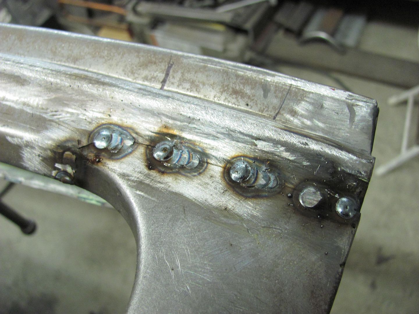
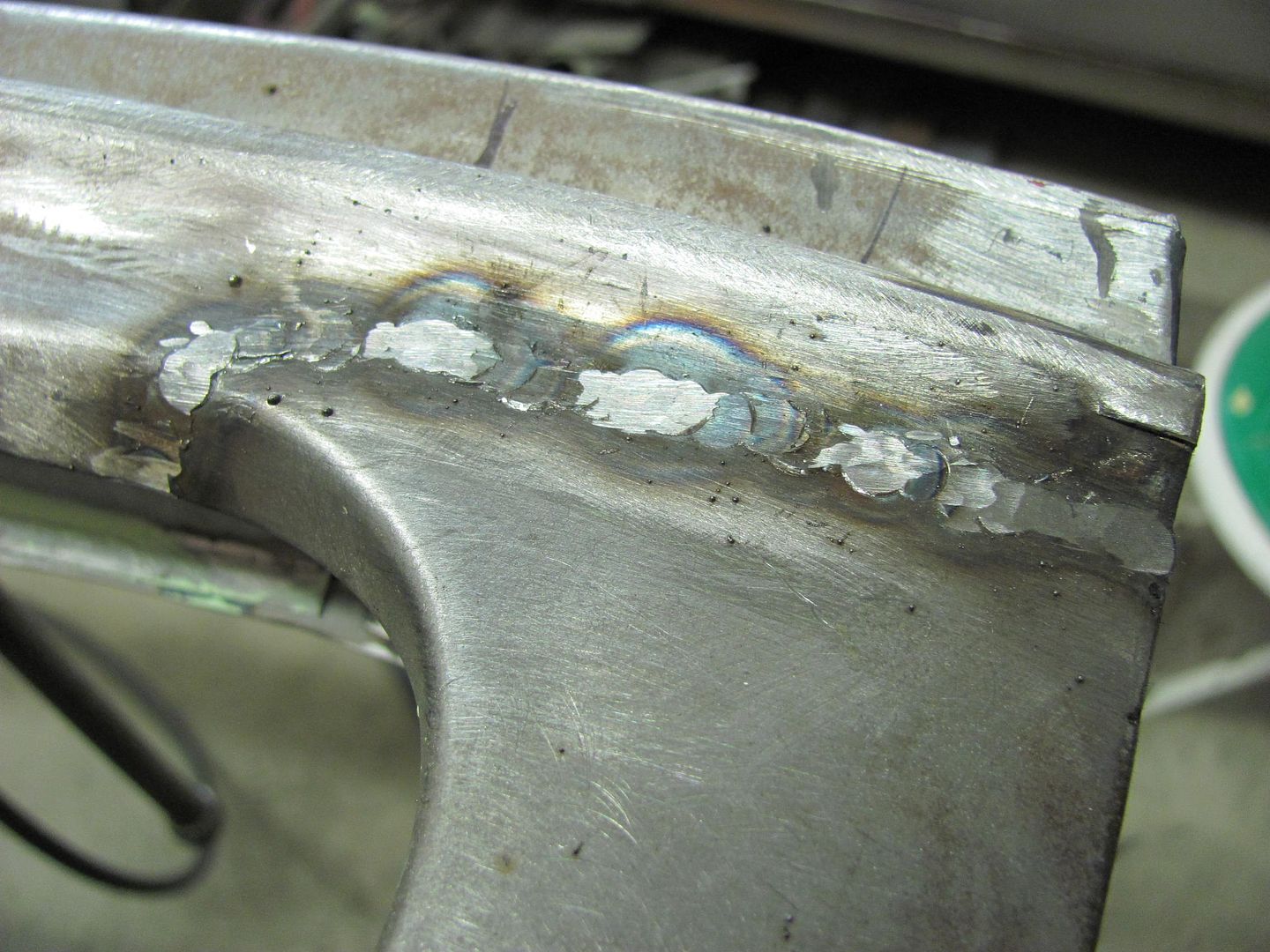
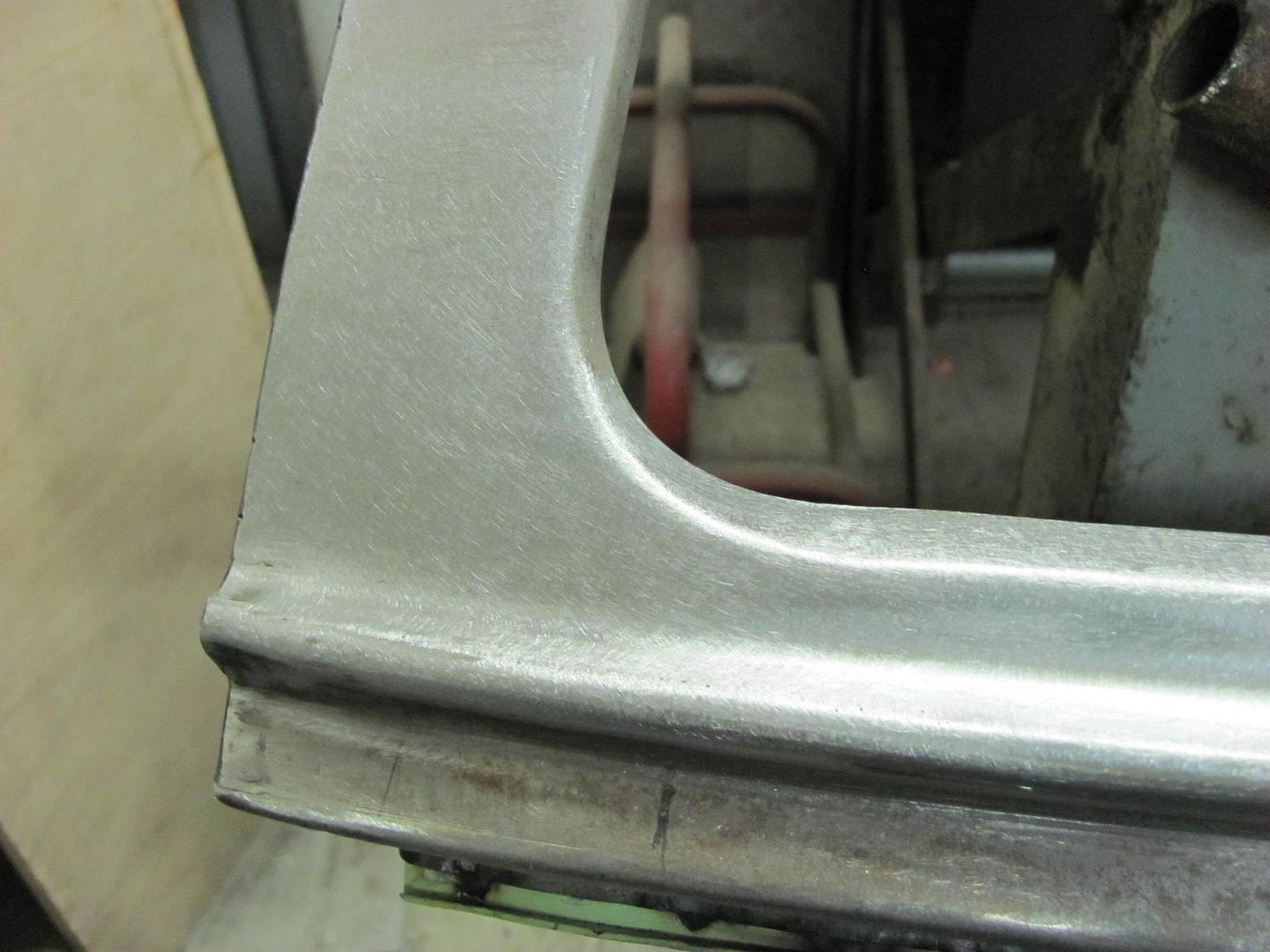
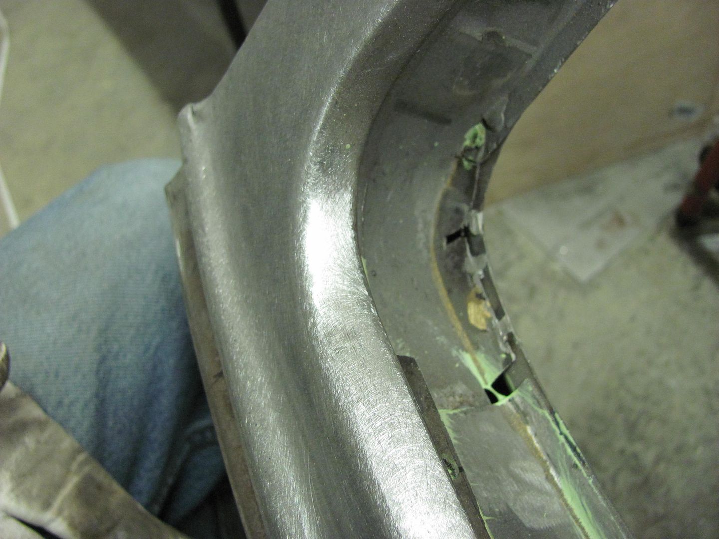
Other side.....
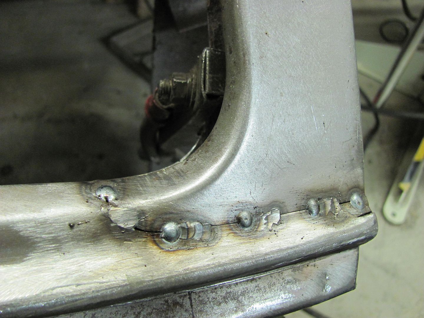
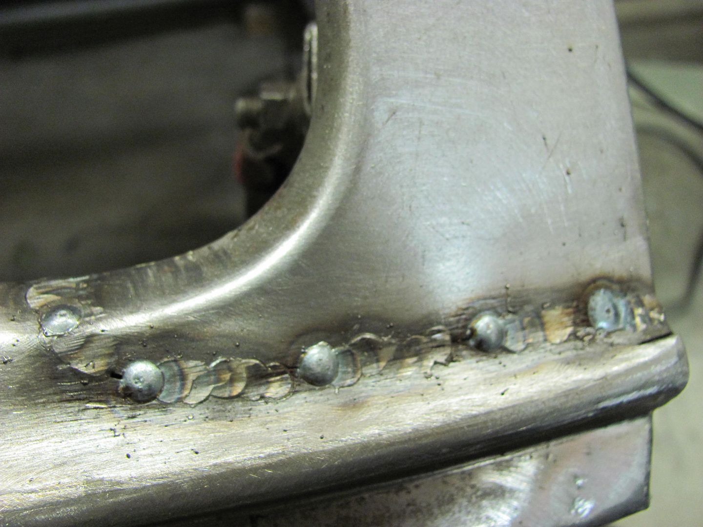
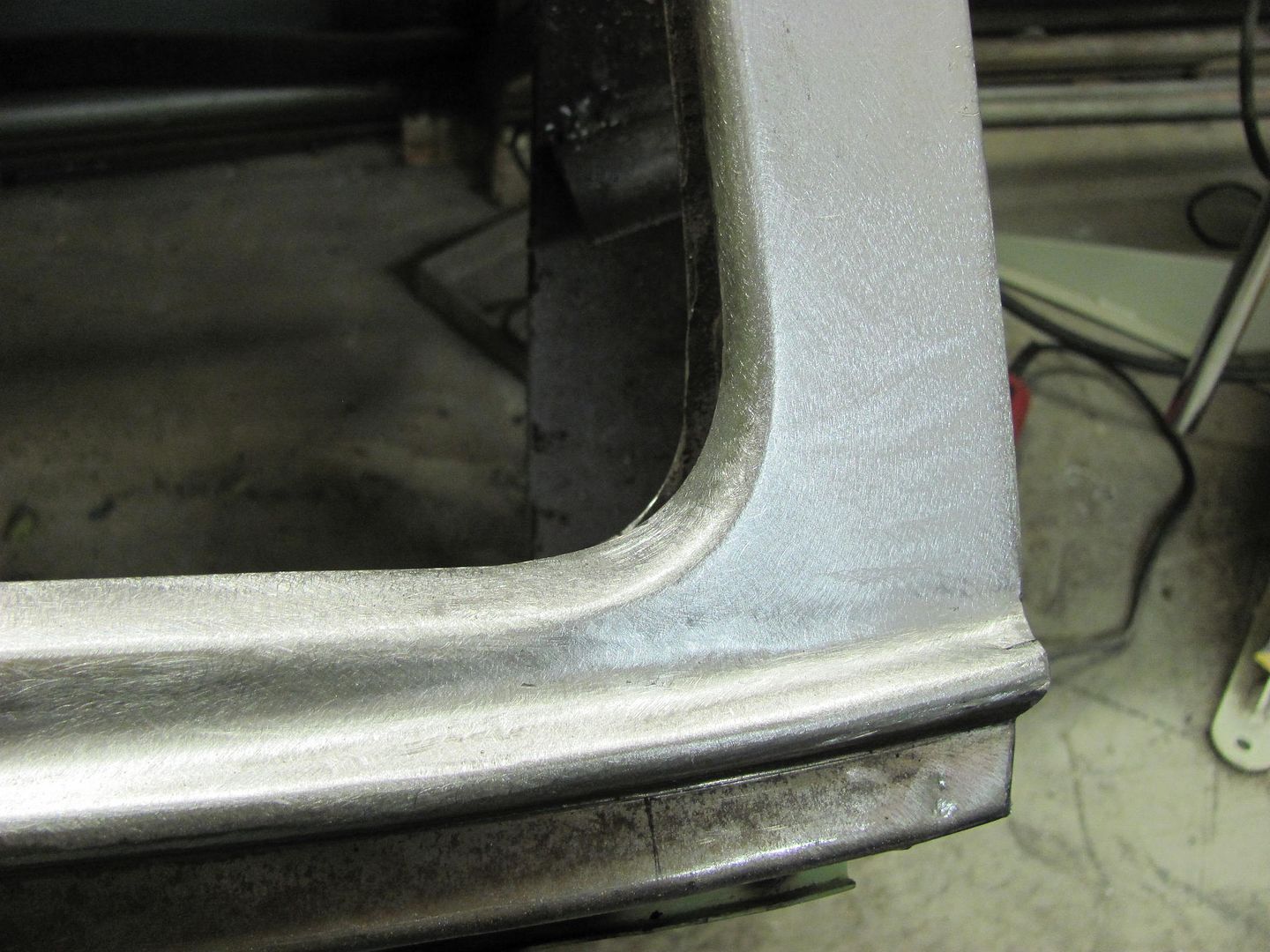
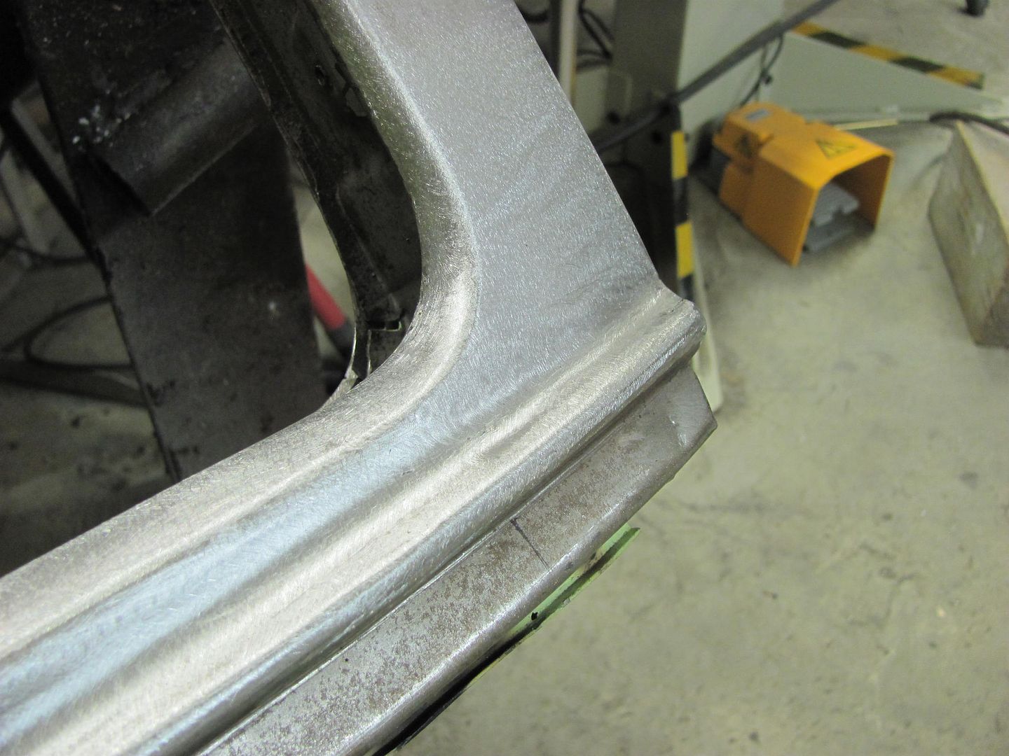
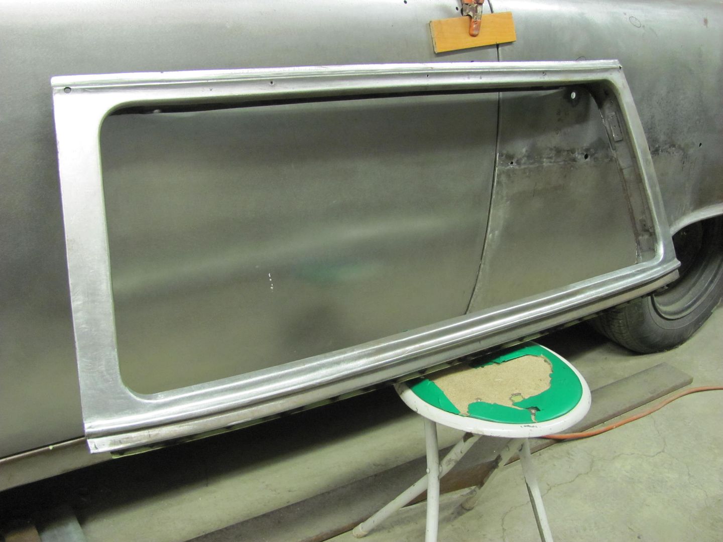
Any imperfection are slight enough that epoxy primer will take care of them. But as you can see, the panel where the weld travels through has a crown that protrudes outward in the horizontal plane, and inward in the vertical plane. So the shrinking forces tended to counteract each other, and the panel stayed exactly where it was. The weld's limited length also help out to limit the shrinking effects. So this shows a good example of using panel profiles in weld placement to limit distortion/panel movement while using the MIG. Similarly, a higher crown that is normally toward the top of a door skin/quarter panel, will tend to hold the shape better than the low crown areas down lower or through the middle, and a bead detail helps even more.Robert
-
12-01-2016 05:48 AM #11
Here's a couple pics showing the grinding and overlap process using the MIG.. Machine's heat settings were just above 16 ga in this case, feed speed slightly higher than machine suggestion for 16 ga, and weld duration about 1 second or so. This tends to give a hotter, flatter weld, but the short duration (trigger pull time) keeps us from blowing any holes..
All clamped up...
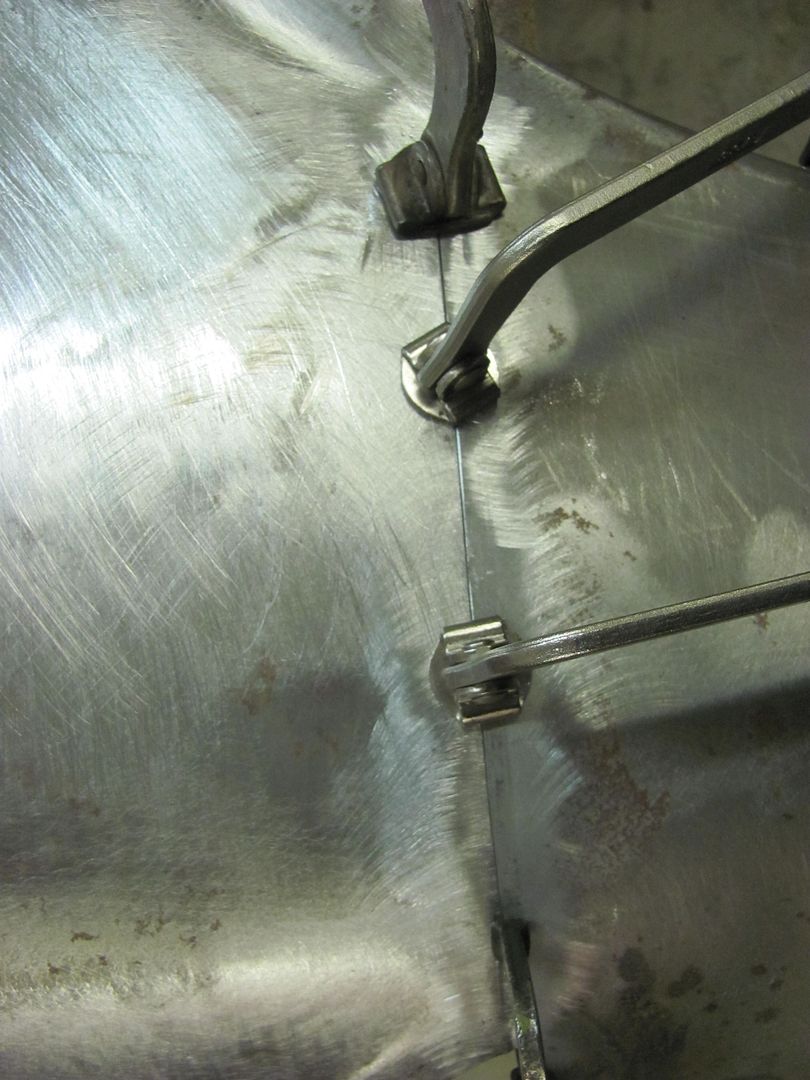
First set of tacks...
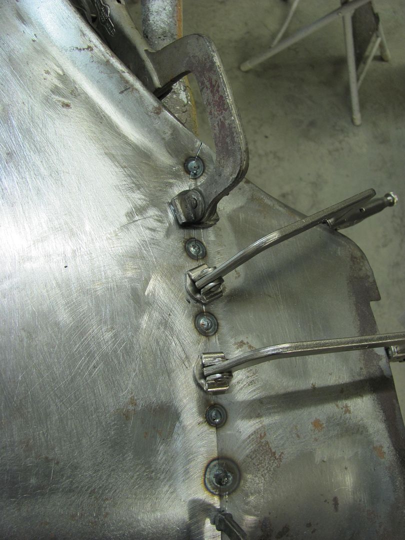
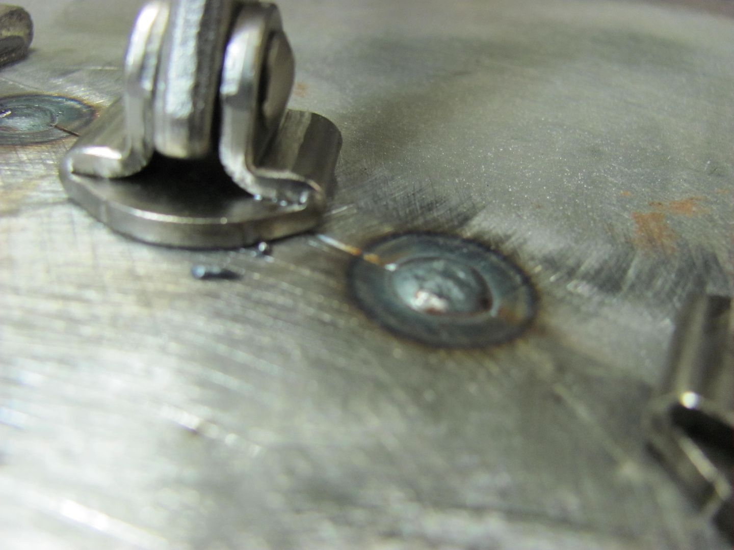
Weld penetration, the back side....
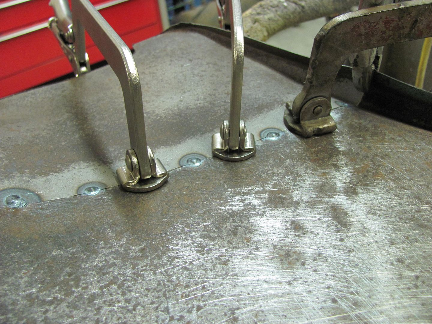
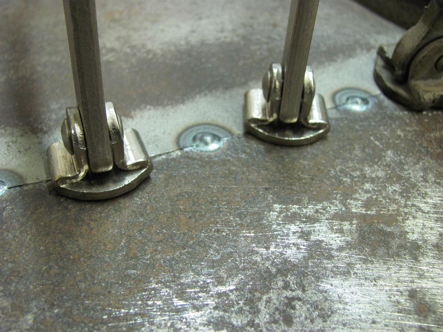
Weld, planish, grind, overlap, repeat... NOTE: grind BOTH front and back, gets those weld dots out of the way for planishing the next set more effectively
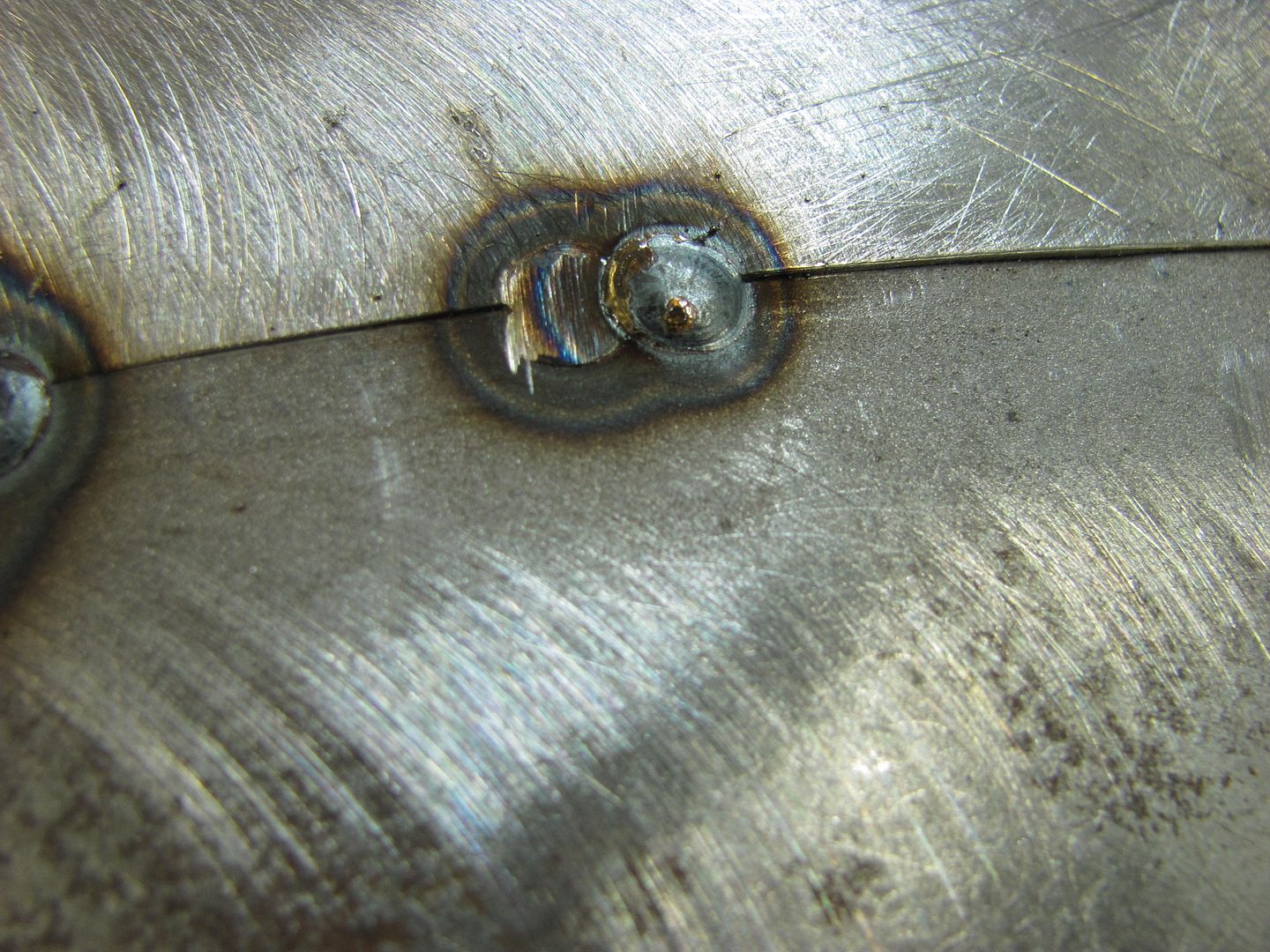
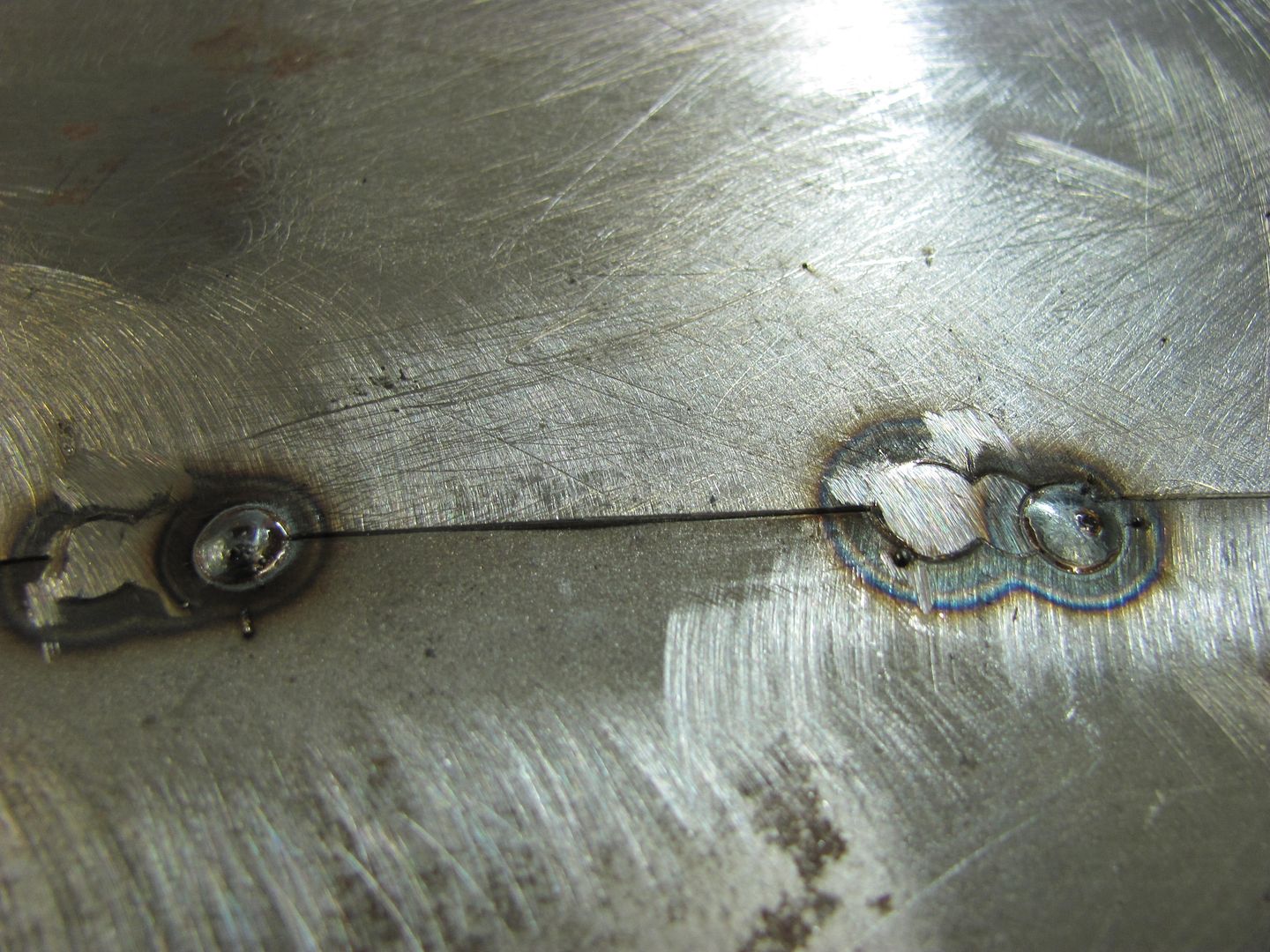
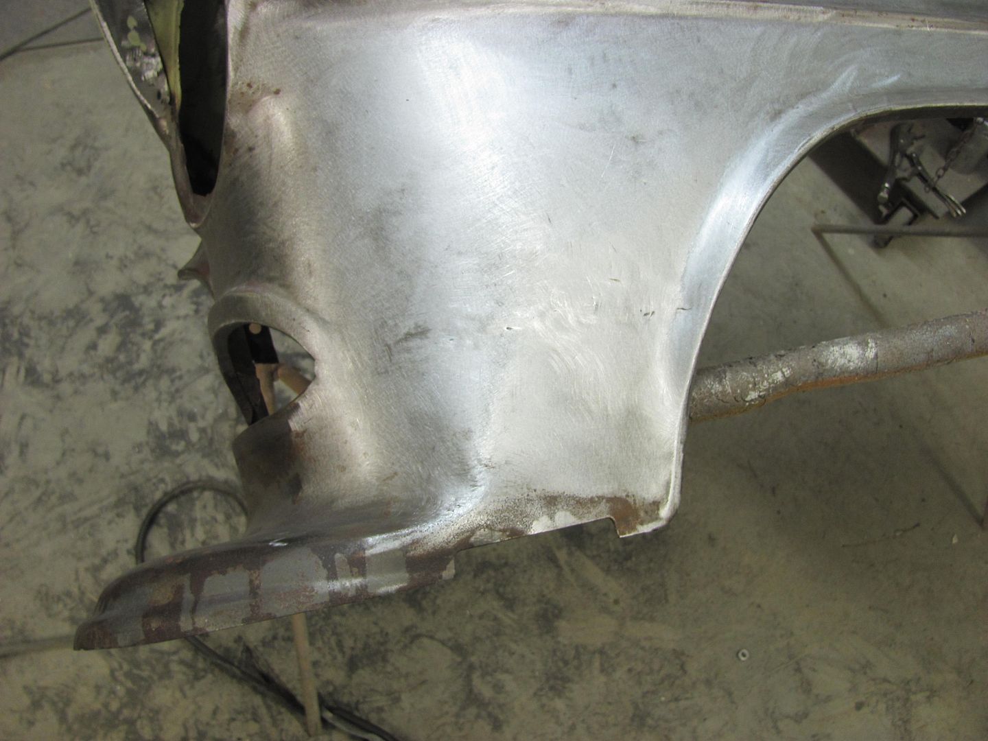
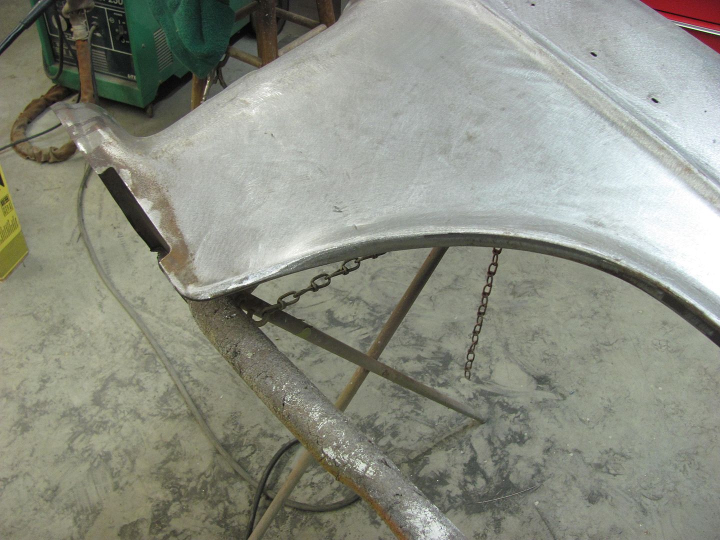
Planishing as you go helps to keep the panel's shape in check...
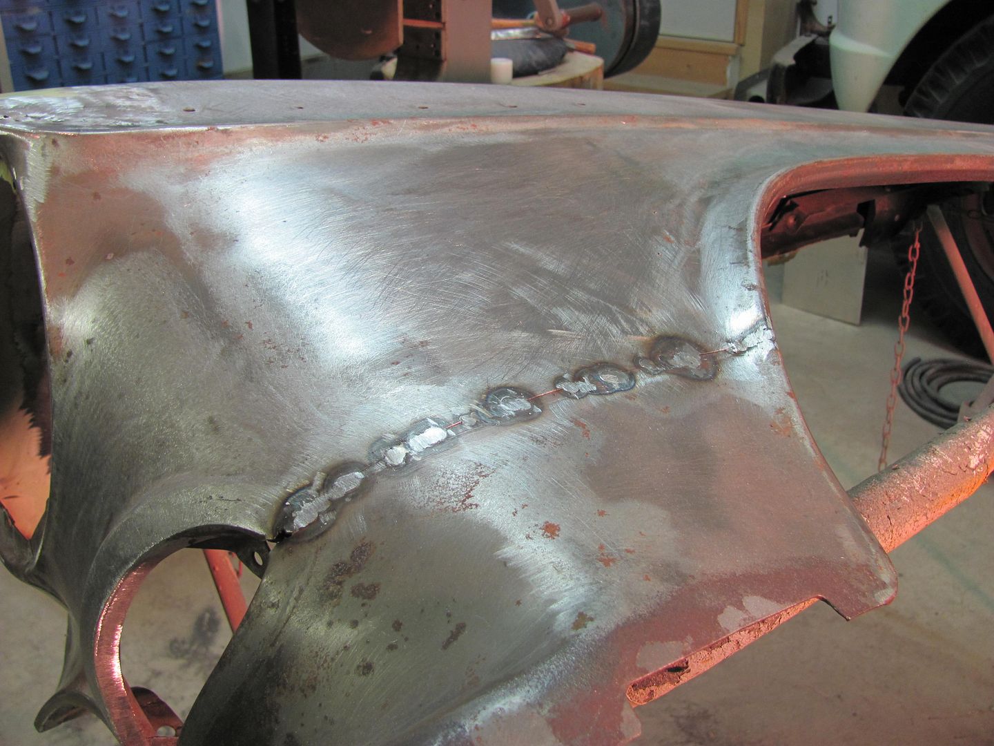
Still needs a bit of metal bumping but not too bad overall..
Last edited by MP&C; 12-01-2016 at 05:56 AM.
Robert
-
12-01-2016 07:42 AM #12
When I was doing rust repair on my 73 charger, I experimented with two techniques which showed promise, maybe MP&C could chime in:
#1 For a patch with no access for planishing, I put an extra bit of crown in the patch. After shrinking, the crown pulls out, effectively preventing the patch from being distorted.
#2 where planishing is accessible, I would put a slight flange on the patch weld seam. During planishing, the flange gets hammered flat, effectively 'stretching' the patch, and compensating for the shrink..
Education is expensive. Keep that in mind, and you'll never be terribly upset when a project goes awry.
EG
-
12-01-2016 08:43 AM #13
I always say use what works for you. In addition to that, always strive for improvement.
The best I have seen is this "no-filler" fusion weld using a TIG machine in this Buick door link below. Absolutely beautiful work and process. Sorry, but you'll need to be a member to view the attachment pictures. Well worth the effort of signing up, as this is about the best process going for door repairs.
Welding buick door - All MetalShaping
In the above link, Richard indicated that he had realized a slight amount of stretch from the serrations of the snips used in cutting the seam. I'm quite sure the edge was touched up with a file to get a perfect seam, but the stretch remained. This slight amount of prestretch was perfect for the MINIMAL amount of shrinking you get with the TIG fusion weld. If it were MIG we would need much more pre-stretch. For your suggestions, I think I would try #1 first, and the amount of stretch needed would be largely determined by the process used. (resulting in trial and error, ie: practice pieces) Anything done in a process should not inflict any more damage to the panel, so I would shy away from the flanging as any creases are more difficult to remove. That's not to say its a "wrong" way to do it, perhaps less preferred due to my perceived notion that it involves extra work. It may in fact require less work, given all the planishing that would be needed otherwise (using MIG). But, referring back to my first statement in this post, use what works for you. And if we're using the MIG, we're dealing with extra work anyhow, let's be honest. If it weren't for you practicing some different methods at the bench in trying to overcome the pitfalls (shrinking from welding) that wouldn't be thrown in the mix as an option. By practicing different methods we find what works the best given the welding process we are using (MIG vs. TIG, filler vs. fusion, etc) The important step for anyone new in the game is understanding what is occurring to be able to make adjustments to deal with any issues. Hence the book I wrote above...
Last edited by MP&C; 12-01-2016 at 08:47 AM.
Robert
-
12-01-2016 09:34 AM #14
-
12-01-2016 10:19 AM #15
Thanks Robert. Your detailed descriptions and guidance are very much appreciated. Just signed up on Allmetalshaping.com and will check out your link.
Attached is a picture of the back of the door.
The rust goes about 5 inches up the door. I have bee using butt welds for my repairs.
1) For the door bottom, would I be better off using a flanger and creating an overlapping flange at the top of the 5" panel?
Welcome to Club Hot Rod! The premier site for
everything to do with Hot Rod, Customs, Low Riders, Rat Rods, and more.
- » Members from all over the US and the world!
- » Help from all over the world for your questions
- » Build logs for you and all members
- » Blogs
- » Image Gallery
- » Many thousands of members and hundreds of thousands of posts!
YES! I want to register an account for free right now! p.s.: For registered members this ad will NOT show


 4Likes

 LinkBack URL
 About LinkBacks
 Reply With Quote


Down all day yesterday, up today, shit or get off the pot.
Where is everybody?